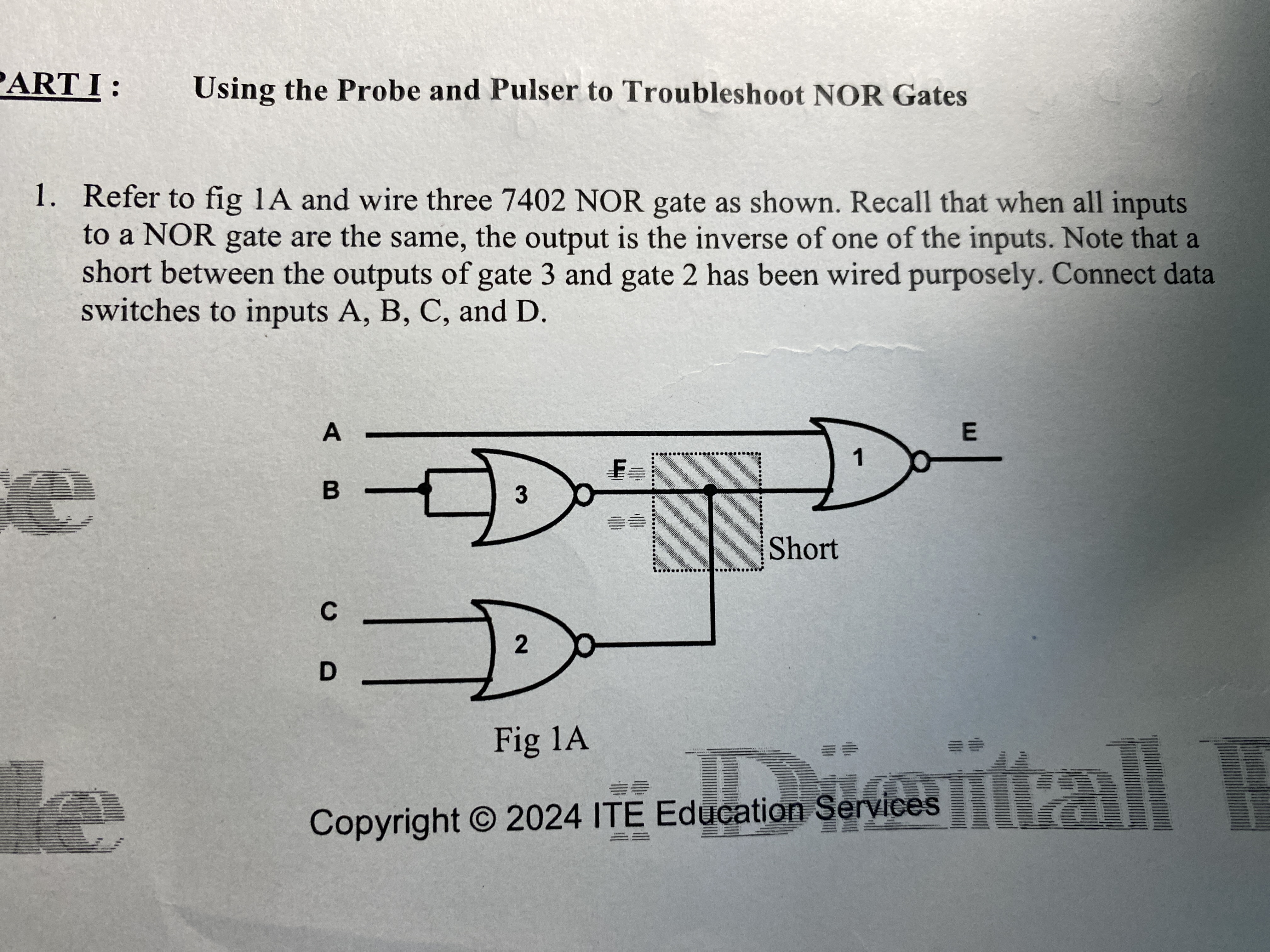
Refer to Fig 1A and wire three 7402 NOR gates as shown. Recall that when all inputs are 0, the output is 1. Note that a short between the outputs of gate 2 has been wired purposely... Refer to Fig 1A and wire three 7402 NOR gates as shown. Recall that when all inputs are 0, the output is 1. Note that a short between the outputs of gate 2 has been wired purposely. Connect data switches to inputs A, B, C, and D.

Understand the Problem
The question is asking us to create a circuit using three 7402 NOR gates according to a diagram provided in the image. The focus is on troubleshooting the NOR gates, understanding their logic, and connecting inputs and outputs properly. We also need to note the specific wiring details mentioned in the text.
Answer
Connect NOR gates per Fig 1A with switches at A, B, C, and D.
Wire three 7402 NOR gates as shown in Fig 1A, connecting switches to inputs A, B, C, and D. Note the short between the outputs of gate 2 and gate 3 before input to gate 1, which outputs E.
Answer for screen readers
Wire three 7402 NOR gates as shown in Fig 1A, connecting switches to inputs A, B, C, and D. Note the short between the outputs of gate 2 and gate 3 before input to gate 1, which outputs E.
More Information
This configuration uses NOR gates, which output true only when all inputs are false, playing on the characteristic property of NOR gates to implement logical functions with negated OR operations.
Tips
Ensure not to confuse inputs and observe the short between outputs of gates 2 and 3.
AI-generated content may contain errors. Please verify critical information