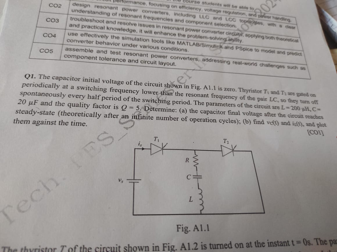
The capacitor initial voltage of the circuit shown in Fig. A1.1 is zero. Thyristor T1 and T2 are gated on periodically at a switching frequency lower than the resonant frequency of... The capacitor initial voltage of the circuit shown in Fig. A1.1 is zero. Thyristor T1 and T2 are gated on periodically at a switching frequency lower than the resonant frequency of the pair LC, so they turn off spontaneously every half period of the switching period. The parameters of the circuit are L = 200 µH, C = 20 µF and the quality factor is Q = 5. Determine: (a) the capacitor final voltage after the circuit reaches steady-state (theoretically after an infinite number of operation cycles); (b) find vc(t) and il(t), and plot them against the time.

Understand the Problem
The question is asking to analyze a given electrical circuit involving capacitors, inductors, and thyristors to determine two specific outcomes: (a) the final voltage across the capacitor after many cycles, and (b) the behavior of the voltage and current over time, requiring a theoretical analysis of the circuit's steady-state conditions.
Answer
Final voltage across the capacitor is given by $V_C = Q \times V_{in}$, and voltage and current over time are $v_C(t) = V_{max} \sin(\omega_0 t + \phi)$ and $i(t) = I_{max} \sin(\omega_0 t + \phi - \frac{\pi}{2})$.
Answer for screen readers
The final voltage across the capacitor in steady-state is given by:
$$ V_C = Q \times V_{in} $$
Assuming $V_{in}$ will determine the maximum steady-state current $I_{max}$.
The functions for voltage and current over time are:
$$ v_C(t) = V_{max} \sin(\omega_0 t + \phi) $$
$$ i(t) = I_{max} \sin(\omega_0 t + \phi - \frac{\pi}{2}) $$
Steps to Solve
- Identify Circuit Parameters
The given parameters are:
- Inductance, $L = 200 , \mu H = 200 \times 10^{-6} , H$
- Capacitance, $C = 20 , \mu F = 20 \times 10^{-6} , F$
- Quality Factor, $Q = 5$
- Calculate Resonant Frequency
The resonant frequency $f_0$ of the LC circuit can be calculated using the formula:
$$ f_0 = \frac{1}{2\pi\sqrt{LC}} $$
- Determine Final Capacitor Voltage
In steady-state, the final voltage across the capacitor (after many cycles) can be calculated. The voltage gain over one cycle in a series resonant circuit can be expressed as:
$$ V_C = Q \times V_{in} $$
Assuming the initial voltage $V_{in}$ is set to zero, this means we need to understand how the thyristors operate to derive the final voltage.
- Analyze Thyristor Behavior
The thyristors are gated on every half period of switching frequency below the resonant frequency. As they turn off, we can expect the capacitor to charge and discharge at this frequency. As it approaches steady-state, we can assume the oscillation reaches a point where the average current through the inductor and capacitor can be determined.
- Determine Current and Voltage Functions
To find the voltage $v_C(t)$ and current $i(t)$ over time, we can use the differential equations governing LCR circuits:
$$ v_C(t) = V_{max} \sin(\omega_0 t + \phi) $$
$$ i(t) = I_{max} \sin(\omega_0 t + \phi - \frac{\pi}{2}) $$
Where:
- $\omega_0 = 2\pi f_0$ is the angular frequency.
- $V_{max}$ and $I_{max}$ would be determined by resonant behavior.
The final voltage across the capacitor in steady-state is given by:
$$ V_C = Q \times V_{in} $$
Assuming $V_{in}$ will determine the maximum steady-state current $I_{max}$.
The functions for voltage and current over time are:
$$ v_C(t) = V_{max} \sin(\omega_0 t + \phi) $$
$$ i(t) = I_{max} \sin(\omega_0 t + \phi - \frac{\pi}{2}) $$
More Information
In steady-state, the circuit will oscillate due to the energy exchange between the inductor and capacitor. The quality factor $Q$ reflects how underdamped the circuit is; a higher $Q$ means less energy loss and clearer sinusoidal oscillations.
Tips
- Forgetting to convert units for inductors and capacitors.
- Misunderstanding the behavior of thyristors and their effect on voltage across the capacitor.
- Assuming linear behavior without considering the effects of resonance.
AI-generated content may contain errors. Please verify critical information