Understand the Problem
The question is asking about a circuit diagram related to a two-step time-to-digital converter. It involves various components such as a pulse generator, calibration circuit, coarse counter, fine counter, and encoding mechanisms. This diagram likely demonstrates how these components interact to convert time intervals into digital values.
Answer
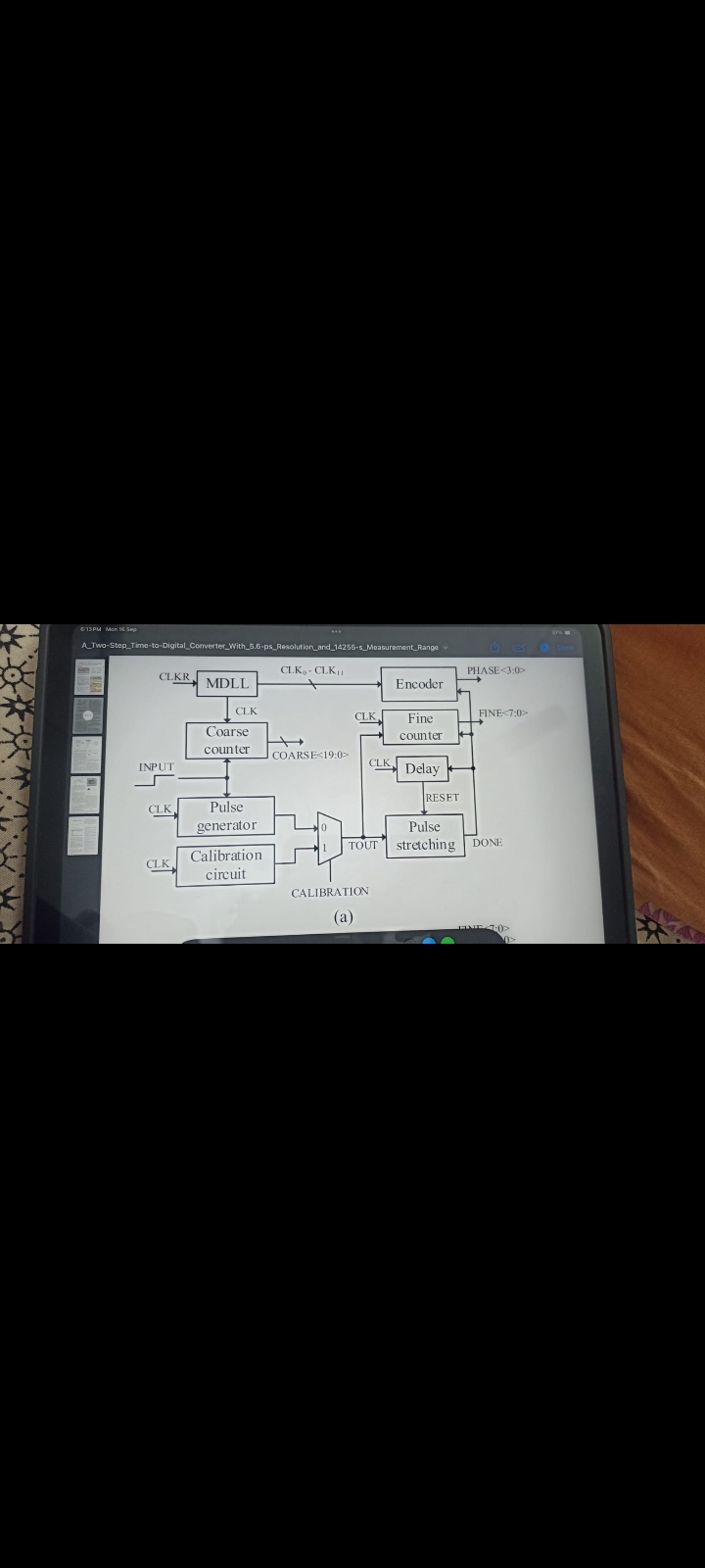
Two-Step Time-to-Digital Converter (TDC) block diagram.
The image shows a block diagram for a Two-Step Time-to-Digital Converter (TDC) with key stages including an MDLL block, coarse counter, pulse generator, calibration circuit, fine counter, pulse stretching, and encoder.
Answer for screen readers
The image shows a block diagram for a Two-Step Time-to-Digital Converter (TDC) with key stages including an MDLL block, coarse counter, pulse generator, calibration circuit, fine counter, pulse stretching, and encoder.
More Information
This type of converter is often used in measuring small time intervals with high precision.
Tips
Make sure to understand the purpose and interconnections of each block in such diagrams.
AI-generated content may contain errors. Please verify critical information