Podcast
Questions and Answers
What is the correct sequence for refitting the coupling tube after inspection?
What is the correct sequence for refitting the coupling tube after inspection?
When should the vacuum interrupters be replaced?
When should the vacuum interrupters be replaced?
What should be visually checked during the maintenance of transition resistors?
What should be visually checked during the maintenance of transition resistors?
What must be assured before refitting the diverter switch insert in the oil compartment?
What must be assured before refitting the diverter switch insert in the oil compartment?
Signup and view all the answers
How often should the varistor connection leads and their fasteners be replaced?
How often should the varistor connection leads and their fasteners be replaced?
Signup and view all the answers
What should be done if signs of leakage paths or discharge marks are observed?
What should be done if signs of leakage paths or discharge marks are observed?
Signup and view all the answers
What is the purpose of aligning the red adjustment mark during coupling tube assembly?
What is the purpose of aligning the red adjustment mark during coupling tube assembly?
Signup and view all the answers
What is the first step in removing the tap-change supervisory control?
What is the first step in removing the tap-change supervisory control?
Signup and view all the answers
What is the significance of checking the mechanical condition of the coupling tube?
What is the significance of checking the mechanical condition of the coupling tube?
Signup and view all the answers
What could result from improperly removing the tap-change supervisory control?
What could result from improperly removing the tap-change supervisory control?
Signup and view all the answers
How many nuts and locking elements may need to be removed from the mounting plate when taking out the tap-change supervisory control?
How many nuts and locking elements may need to be removed from the mounting plate when taking out the tap-change supervisory control?
Signup and view all the answers
What is the purpose of the Teflon strip mentioned in the removal process?
What is the purpose of the Teflon strip mentioned in the removal process?
Signup and view all the answers
What action should be taken with the oil suction pipe before removal?
What action should be taken with the oil suction pipe before removal?
Signup and view all the answers
What should be done with the lead of the tap-change supervisory control before pulling out the diverter switch insert?
What should be done with the lead of the tap-change supervisory control before pulling out the diverter switch insert?
Signup and view all the answers
Which of the following is NOT a step in removing the tap-change supervisory control?
Which of the following is NOT a step in removing the tap-change supervisory control?
Signup and view all the answers
What is the primary risk associated with removing the tap-change supervisory control without care?
What is the primary risk associated with removing the tap-change supervisory control without care?
Signup and view all the answers
What should be done with lock tabs, lock disks, lock nuts, and the on-load tap-changer head cover o-ring after removal?
What should be done with lock tabs, lock disks, lock nuts, and the on-load tap-changer head cover o-ring after removal?
Signup and view all the answers
Which type of screws should be used with the on-load tap-changer?
Which type of screws should be used with the on-load tap-changer?
Signup and view all the answers
How should the diverter switch insert's energy accumulator be positioned before insertion?
How should the diverter switch insert's energy accumulator be positioned before insertion?
Signup and view all the answers
What is required for the alignment of the diverter switch insert during installation?
What is required for the alignment of the diverter switch insert during installation?
Signup and view all the answers
What should be ensured about the screw connection points before installing components?
What should be ensured about the screw connection points before installing components?
Signup and view all the answers
What is the consequence of correctly aligning the diverter switch insert?
What is the consequence of correctly aligning the diverter switch insert?
Signup and view all the answers
Which of the following is NOT a recommended practice for installing the diverter switch insert?
Which of the following is NOT a recommended practice for installing the diverter switch insert?
Signup and view all the answers
What must be checked before lowering the diverter switch insert into the oil compartment?
What must be checked before lowering the diverter switch insert into the oil compartment?
Signup and view all the answers
What is the correct distance between the upper edge of the diverter switch insert coupling tube and the head flange during installation?
What is the correct distance between the upper edge of the diverter switch insert coupling tube and the head flange during installation?
Signup and view all the answers
What is the first step in the correct order of installation for the oil suction pipe?
What is the first step in the correct order of installation for the oil suction pipe?
Signup and view all the answers
What must be installed before the oil suction pipe according to the installation order?
What must be installed before the oil suction pipe according to the installation order?
Signup and view all the answers
What is the purpose of the locking washers when securing the mounting plate?
What is the purpose of the locking washers when securing the mounting plate?
Signup and view all the answers
What should be checked to ensure the tap-change supervisory control is installed correctly?
What should be checked to ensure the tap-change supervisory control is installed correctly?
Signup and view all the answers
Which part is directly fastened to the retaining bracket during the installation process?
Which part is directly fastened to the retaining bracket during the installation process?
Signup and view all the answers
What must be connected outside its bracket during the final steps of installation?
What must be connected outside its bracket during the final steps of installation?
Signup and view all the answers
What damage is explicitly mentioned as a risk during improper installation?
What damage is explicitly mentioned as a risk during improper installation?
Signup and view all the answers
What is the first step to collect drained oil from the on-load tap-changer?
What is the first step to collect drained oil from the on-load tap-changer?
Signup and view all the answers
What must be done before opening the head cover of the on-load tap-changer?
What must be done before opening the head cover of the on-load tap-changer?
Signup and view all the answers
Which auxiliary circuits must be de-energized to prevent hazards?
Which auxiliary circuits must be de-energized to prevent hazards?
Signup and view all the answers
What action should be taken after approximately 10 liters of oil have been drained?
What action should be taken after approximately 10 liters of oil have been drained?
Signup and view all the answers
What precaution is necessary regarding the sealing surfaces when removing the head cover?
What precaution is necessary regarding the sealing surfaces when removing the head cover?
Signup and view all the answers
Why is it important to avoid operating electric devices during the maintenance procedure?
Why is it important to avoid operating electric devices during the maintenance procedure?
Signup and view all the answers
What should be ensured about the o-ring during maintenance?
What should be ensured about the o-ring during maintenance?
Signup and view all the answers
What might occur if parts fall into the diverter switch oil compartment?
What might occur if parts fall into the diverter switch oil compartment?
Signup and view all the answers
Abbreviations such as OI, DS, and MC stand for Operating Instructions, Diverter Switch, and Main Contact respectively.
Abbreviations such as OI, DS, and MC stand for Operating Instructions, Diverter Switch, and Main Contact respectively.
Signup and view all the answers
The highest voltage for equipment, represented as Um, is measured in watts.
The highest voltage for equipment, represented as Um, is measured in watts.
Signup and view all the answers
The symbol for 'Fill with oil' appears in the notation conventions section of the technical documentation.
The symbol for 'Fill with oil' appears in the notation conventions section of the technical documentation.
Signup and view all the answers
The signal word DANGER indicates a situation that, if not avoided, could lead to minor injuries.
The signal word DANGER indicates a situation that, if not avoided, could lead to minor injuries.
Signup and view all the answers
The notation conventions section is primarily concerned with legal and binding regulations.
The notation conventions section is primarily concerned with legal and binding regulations.
Signup and view all the answers
Hazard communication in the technical file uses a format that includes warnings and specifies actions to take.
Hazard communication in the technical file uses a format that includes warnings and specifies actions to take.
Signup and view all the answers
TDCa and TDCb refer to on-load tap-changer indicators.
TDCa and TDCb refer to on-load tap-changer indicators.
Signup and view all the answers
The implication of a tightening torque symbol in the documentation is related to proper maintenance practices.
The implication of a tightening torque symbol in the documentation is related to proper maintenance practices.
Signup and view all the answers
The maintenance manual (MM) is not listed as an abbreviation in the document.
The maintenance manual (MM) is not listed as an abbreviation in the document.
Signup and view all the answers
Environmental protection regulations must be disregarded during operation and maintenance.
Environmental protection regulations must be disregarded during operation and maintenance.
Signup and view all the answers
The term 'Caution' indicates a situation that could result in death or serious injury.
The term 'Caution' indicates a situation that could result in death or serious injury.
Signup and view all the answers
Pictograms in warning notices can indicate the presence of combustible substances.
Pictograms in warning notices can indicate the presence of combustible substances.
Signup and view all the answers
The information system described is aimed at complicating the understanding of procedures.
The information system described is aimed at complicating the understanding of procedures.
Signup and view all the answers
Reading the technical file carefully is necessary to familiarize oneself with the product.
Reading the technical file carefully is necessary to familiarize oneself with the product.
Signup and view all the answers
A 'Notice' signal indicates measures to be taken to prevent life-threatening situations.
A 'Notice' signal indicates measures to be taken to prevent life-threatening situations.
Signup and view all the answers
Warning of dangerous electrical voltage is illustrated with a specific pictogram.
Warning of dangerous electrical voltage is illustrated with a specific pictogram.
Signup and view all the answers
Warnings about tipping hazards are conveyed through specific warning notices.
Warnings about tipping hazards are conveyed through specific warning notices.
Signup and view all the answers
The general safety information chapter in the technical file contains trivial details.
The general safety information chapter in the technical file contains trivial details.
Signup and view all the answers
The maximum permitted measured current for a filled oil compartment is 10 A DC.
The maximum permitted measured current for a filled oil compartment is 10 A DC.
Signup and view all the answers
DC resistance measurement requires that the measured current must be 0 A when changing the operating position.
DC resistance measurement requires that the measured current must be 0 A when changing the operating position.
Signup and view all the answers
The measured DC current can be up to 100% of the rated current of the transformer winding to ensure accurate measurements.
The measured DC current can be up to 100% of the rated current of the transformer winding to ensure accurate measurements.
Signup and view all the answers
Operating conditions for on-load tap-changers can be monitored without interruption of measured current at all times.
Operating conditions for on-load tap-changers can be monitored without interruption of measured current at all times.
Signup and view all the answers
The DC resistance measurement process is the same for both empty and oil-filled compartments.
The DC resistance measurement process is the same for both empty and oil-filled compartments.
Signup and view all the answers
The DC current restriction during measurement is primarily for safety and to maintain the integrity of the transformer.
The DC current restriction during measurement is primarily for safety and to maintain the integrity of the transformer.
Signup and view all the answers
The maximum measured DC current in an oil compartment empty is 50 A.
The maximum measured DC current in an oil compartment empty is 50 A.
Signup and view all the answers
DC resistance measurement can be performed continuously without any need to stop the measured current.
DC resistance measurement can be performed continuously without any need to stop the measured current.
Signup and view all the answers
The highest voltage for the VRC OLTC variant is 175 kV.
The highest voltage for the VRC OLTC variant is 175 kV.
Signup and view all the answers
The motor-drive unit can be operated while the on-load tap-changer is not coupled without risking damage.
The motor-drive unit can be operated while the on-load tap-changer is not coupled without risking damage.
Signup and view all the answers
The maximum weight limit for the diverter switch insert is 120 kg.
The maximum weight limit for the diverter switch insert is 120 kg.
Signup and view all the answers
The withdrawal height of the diverter switch insert during maintenance is measured in liters.
The withdrawal height of the diverter switch insert during maintenance is measured in liters.
Signup and view all the answers
The oil quantity for oil change in the VRF OLTC variant is stated in liters.
The oil quantity for oil change in the VRF OLTC variant is stated in liters.
Signup and view all the answers
The oil change for the VRE OLTC variant requires a quantity of 1380 liters.
The oil change for the VRE OLTC variant requires a quantity of 1380 liters.
Signup and view all the answers
The maximum withdrawal height for VRD OLTC variant during maintenance is 1840 mm.
The maximum withdrawal height for VRD OLTC variant during maintenance is 1840 mm.
Signup and view all the answers
It is acceptable to not block the motor-drive unit against electrical operation during adjustments.
It is acceptable to not block the motor-drive unit against electrical operation during adjustments.
Signup and view all the answers
Filling the diverter switch oil compartment with insulating oil should reach the lower edge of the coupling shaft.
Filling the diverter switch oil compartment with insulating oil should reach the lower edge of the coupling shaft.
Signup and view all the answers
A damaged o-ring can lead to oil escaping from the on-load tap-changer, causing potential damage.
A damaged o-ring can lead to oil escaping from the on-load tap-changer, causing potential damage.
Signup and view all the answers
The on-load tap-changer head cover can be sealed with a screw cap without any specific tightening torque requirement.
The on-load tap-changer head cover can be sealed with a screw cap without any specific tightening torque requirement.
Signup and view all the answers
It is acceptable to skip cleaning the sealing surfaces before placing the on-load tap-changer head cover.
It is acceptable to skip cleaning the sealing surfaces before placing the on-load tap-changer head cover.
Signup and view all the answers
The venting process only applies to the on-load tap-changer head and does not involve the oil conservator.
The venting process only applies to the on-load tap-changer head and does not involve the oil conservator.
Signup and view all the answers
It is essential to match the red triangular marks on both the on-load tap-changer head and cover during assembly.
It is essential to match the red triangular marks on both the on-load tap-changer head and cover during assembly.
Signup and view all the answers
The dielectric strength and water content of insulating oil are irrelevant as long as oil is present in the diverter switch.
The dielectric strength and water content of insulating oil are irrelevant as long as oil is present in the diverter switch.
Signup and view all the answers
The vent pipe connection S on the on-load tap-changer head does not need to be closed again after venting.
The vent pipe connection S on the on-load tap-changer head does not need to be closed again after venting.
Signup and view all the answers
Study Notes
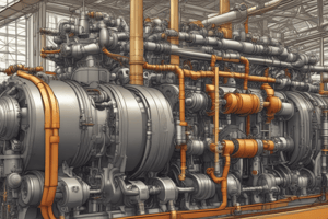
Maintenance of On-Load Tap-Changer
- Place a bucket (10 liters) under the drain valve to collect drained oil before opening the drain valve.
- Use a screwdriver to lift the valve tappet on air-vent valve E1; oil level will decrease automatically.
- Close the drain valve after draining approximately 10 liters of oil; securely seal air-vent valve E1 with a screw cap.
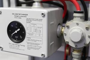
De-energizing Tap-Change Supervisory Control
- If equipped, de-energize the tap-change supervisory control before opening the head cover.
- Ensure all circuits, including auxiliary devices, are de-energized to prevent accidents.
Removing On-Load Tap-Changer Head Cover
- Loosen screws with locking washers on the head cover to remove it.
- Check sealing surfaces and o-rings for sound condition; ensure no parts fall into the diverter switch oil compartment.
Handling Tap-Change Supervisory Control
- Remove the tap-change supervisory control carefully to avoid damaging connecting leads.
- Disconnect the plug connector and remove mounting nuts and locking elements.
- Take out the supervisory control along with the mounting plate and drive shaft.
Removing Oil Suction Pipe
- Detach cable ties from the oil suction pipe and pull it out of the on-load tap-changer head.
- Swivel the lead of the tap-change supervisory control to avoid damage while extracting the diverter switch insert.
Visual Inspection and Maintenance
- Perform a thorough visual inspection of the coupling tube for mechanical or electrical damage.
- Ensure proper alignment of adjustment marks during reassembly of the coupling tube.
Inspections and Replacements
- Visually check transition resistors for unusual appearances.
- Replace vacuum interrupters after 600,000 tap change operations; consult MR Technical Service for assistance.
- Verify that all six insulating shims are present before reassembling parts.
Installation Precautions
- Only use new lock tabs, nuts, and screws once; ensure screw connections are free from oil and grease.
- Follow the correct order of installation to prevent damage to components.
Inserting Diverter Switch Insert
- Ensure the tap selector coupling is in the correct adjustment position before inserting the diverter switch.
- Position the diverter switch insert to align red markings on the energy accumulator and tap-changer head.
- Check that the distance between coupling tube and head flange is approximately 10 ± 2 mm.
Final Assembly Steps
- Insert the oil suction pipe and secure it with a cable tie on the retaining bracket.
- Reinstall the tap-change supervisory control with correct seating of the drive shaft feather key and secure the mounting plate with nuts and washers.
Legal and Compliance Requirements
- Compliance with European and national laws, including accident prevention and environmental protection regulations, is mandatory.
- Technical files and supporting documents must always be accessible for future reference.
Notation Conventions
- Abbreviations define specific terms related to the equipment:
- OI: Operating instructions
- DS: Diverter switch
- OLTC: On-load tap-changer
- MR: Maschinenfabrik Reinhausen GmbH
- Symbols indicate actions or specifications, such as tightening torque, visual inspections, and use of tools.
Hazard Communication System
- Warnings follow a standard format: type of danger, consequences, and recommended actions.
- Signal words indicate severity:
- DANGER: Risk of death or severe injury.
- WARNING: Could result in serious injury.
- CAUTION: Risks minor injuries.
- NOTICE: Prevents property damage.
- Pictograms visually represent dangers, such as electrical voltage or combustible substances.
General Safety Information
- Detailed maintenance instructions are crucial for safe operation.
- Emphasis on understanding the technical file for effective maintenance practices.
Maintenance Scope and Intervals
- DC resistance measurements should not exceed defined limits to avoid transformer overheating.
- Maximum measured currents vary based on the oil compartment state:
- Empty: Maximum of 10 A DC.
- Filled: Maximum of 50 A DC.
Preparatory Work for Maintenance
- Use of a crane or MR lifting device is necessary for the safe handling of the diverter switch insert, which has a maximum weight of 120 kg.
- Procedures must ensure that the motor-drive unit is not activated unless coupled to avoid equipment damage.
- Important measures include filling oil compartments appropriately, replacing O-rings to prevent oil leaks, and maintaining clean sealing surfaces.
Oil Quantity and Maintenance Details
- Specific oil quantities for different OLTC variants are provided, depending on the highest voltage for equipment.
- The importance of maintaining adequate dielectric strength and water content in insulating oil to prevent transformer and on-load tap-changer damage is emphasized.
Steps for Inserting Diverter Switch Insert
- Move on-load tap-changer to the adjustment position, record current operating position, and ensure proper filling of insulating oil.
- Installation and tightening procedures for the on-load tap-changer head cover must be followed precisely to avoid leaks and ensure proper sealing.
Studying That Suits You
Use AI to generate personalized quizzes and flashcards to suit your learning preferences.
Related Documents
Description
This quiz covers essential procedures for maintaining an on-load tap-changer. It includes steps for draining oil, de-energizing supervisory control, and removing the head cover for inspection. Understanding these processes is crucial for ensuring operational safety and efficiency.