Podcast
Questions and Answers
What is the primary function of ETOS?
What is the primary function of ETOS?
What is the purpose of the service port on the ETOS unit?
What is the purpose of the service port on the ETOS unit?
What is the default IP address of the ETOS system?
What is the default IP address of the ETOS system?
Where do you select the location to export the operating instructions to?
Where do you select the location to export the operating instructions to?
Signup and view all the answers
What type of cable is needed to connect to ETOS for the first time?
What type of cable is needed to connect to ETOS for the first time?
Signup and view all the answers
What is the format of the exported operating instructions file?
What is the format of the exported operating instructions file?
Signup and view all the answers
Which ETOS module is required for monitoring torque and bushing?
Which ETOS module is required for monitoring torque and bushing?
Signup and view all the answers
What is the purpose of the SW-33 card in ETOS?
What is the purpose of the SW-33 card in ETOS?
Signup and view all the answers
Which of the following ETOS modules has 42 digital input contacts and 20 outputs?
Which of the following ETOS modules has 42 digital input contacts and 20 outputs?
Signup and view all the answers
What is the function of the backplane in ETOS?
What is the function of the backplane in ETOS?
Signup and view all the answers
What type of signals can be input and output using the AIO cards?
What type of signals can be input and output using the AIO cards?
Signup and view all the answers
Which ETOS module is the heart of the system and holds all the software and data?
Which ETOS module is the heart of the system and holds all the software and data?
Signup and view all the answers
What is the purpose of the VI card in ETOS?
What is the purpose of the VI card in ETOS?
Signup and view all the answers
How many digital input contacts and outputs does the DIO 2815 have?
How many digital input contacts and outputs does the DIO 2815 have?
Signup and view all the answers
What is a characteristic of the ETOS visualization?
What is a characteristic of the ETOS visualization?
Signup and view all the answers
What is displayed in the functional section of the home screen?
What is displayed in the functional section of the home screen?
Signup and view all the answers
What is the purpose of the navigation bar?
What is the purpose of the navigation bar?
Signup and view all the answers
What is available at all times on the screen?
What is available at all times on the screen?
Signup and view all the answers
What is featured on the administrative bar?
What is featured on the administrative bar?
Signup and view all the answers
What can be accessed through the MR logo on the administrative bar?
What can be accessed through the MR logo on the administrative bar?
Signup and view all the answers
What is the primary purpose of the Import and Export Manager in ETOS?
What is the primary purpose of the Import and Export Manager in ETOS?
Signup and view all the answers
What type of file contains a full picture of the device, including history, settings, and historic data?
What type of file contains a full picture of the device, including history, settings, and historic data?
Signup and view all the answers
What is the primary purpose of the Settings.RHI file?
What is the primary purpose of the Settings.RHI file?
Signup and view all the answers
What restriction is applied to software imports in ETOS?
What restriction is applied to software imports in ETOS?
Signup and view all the answers
What type of files can be modified and re-imported in ETOS?
What type of files can be modified and re-imported in ETOS?
Signup and view all the answers
What is the primary purpose of the Event Memory file in ETOS?
What is the primary purpose of the Event Memory file in ETOS?
Signup and view all the answers
What is the primary purpose of checking for historic data and programs in the logic editor of ETAS during the software update process?
What is the primary purpose of checking for historic data and programs in the logic editor of ETAS during the software update process?
Signup and view all the answers
What is the consequence of interrupting the power supply to ETOS during the software update?
What is the consequence of interrupting the power supply to ETOS during the software update?
Signup and view all the answers
What happens to the device after the software update is complete?
What happens to the device after the software update is complete?
Signup and view all the answers
What is the purpose of the 'Retain Settings' screen during the software update process?
What is the purpose of the 'Retain Settings' screen during the software update process?
Signup and view all the answers
What can be carried out after the initial update process if hardware modifications are required?
What can be carried out after the initial update process if hardware modifications are required?
Signup and view all the answers
What is required to perform a software update on ATOS?
What is required to perform a software update on ATOS?
Signup and view all the answers
Where can you find the unique wiring diagram of a Heatos unit?
Where can you find the unique wiring diagram of a Heatos unit?
Signup and view all the answers
What type of signals are typically represented in the lower section of each page in the wiring diagram?
What type of signals are typically represented in the lower section of each page in the wiring diagram?
Signup and view all the answers
What is the purpose of the digital input contacts in the Heatos system?
What is the purpose of the digital input contacts in the Heatos system?
Signup and view all the answers
What type of sensors can be connected to the Heatos system in 2-, 3-, or 4-wire mode?
What type of sensors can be connected to the Heatos system in 2-, 3-, or 4-wire mode?
Signup and view all the answers
What is the function of the measurement cards in the Heatos system?
What is the function of the measurement cards in the Heatos system?
Signup and view all the answers
What type of signals can be displayed on devices driven by 4-20 milliamp or 0-10 volt signals?
What type of signals can be displayed on devices driven by 4-20 milliamp or 0-10 volt signals?
Signup and view all the answers
What is the primary purpose of the DIO configuration section in Ethos?
What is the primary purpose of the DIO configuration section in Ethos?
Signup and view all the answers
What does the Function column in the DIO configuration table indicate?
What does the Function column in the DIO configuration table indicate?
Signup and view all the answers
What type of signals can be freely customized by users in Ethos?
What type of signals can be freely customized by users in Ethos?
Signup and view all the answers
In which section of the Ethos home screen can users access the DIO configuration?
In which section of the Ethos home screen can users access the DIO configuration?
Signup and view all the answers
What is the purpose of the Assembly and Channel columns in the DIO configuration table?
What is the purpose of the Assembly and Channel columns in the DIO configuration table?
Signup and view all the answers
Where can users find a list of available signals on the unit in Ethos?
Where can users find a list of available signals on the unit in Ethos?
Signup and view all the answers
What is the primary function of the gearbox icon in the channel configuration?
What is the primary function of the gearbox icon in the channel configuration?
Signup and view all the answers
What type of signals can be displayed on devices driven by General Purpose Analog In (GPAI) signals?
What type of signals can be displayed on devices driven by General Purpose Analog In (GPAI) signals?
Signup and view all the answers
What is the purpose of scaling in the channel configuration?
What is the purpose of scaling in the channel configuration?
Signup and view all the answers
What type of sensors can be connected to the Ethos system in 2-, 3-, or 4-wire mode?
What type of sensors can be connected to the Ethos system in 2-, 3-, or 4-wire mode?
Signup and view all the answers
What is the primary purpose of the channel column in the AIO configuration?
What is the primary purpose of the channel column in the AIO configuration?
Signup and view all the answers
What type of signals can be configured using General Purpose Analog Out (GPAO) signals?
What type of signals can be configured using General Purpose Analog Out (GPAO) signals?
Signup and view all the answers
What is the primary purpose of the event log in Ethos?
What is the primary purpose of the event log in Ethos?
Signup and view all the answers
What feature is available in the recorder to analyze the data further?
What feature is available in the recorder to analyze the data further?
Signup and view all the answers
What can be filtered in the event log?
What can be filtered in the event log?
Signup and view all the answers
What type of values are displayed in the recorder?
What type of values are displayed in the recorder?
Signup and view all the answers
What can be exported from the settings?
What can be exported from the settings?
Signup and view all the answers
What is a characteristic of the event screen?
What is a characteristic of the event screen?
Signup and view all the answers
What is the primary reason for encrypting the communication in Etheros?
What is the primary reason for encrypting the communication in Etheros?
Signup and view all the answers
What is the correct sequence for expanding the Etheros system?
What is the correct sequence for expanding the Etheros system?
Signup and view all the answers
What is the significance of the purple cable connecting the CPU and Dio modules?
What is the significance of the purple cable connecting the CPU and Dio modules?
Signup and view all the answers
What is the primary reason for clearing the browser cache in Etheros?
What is the primary reason for clearing the browser cache in Etheros?
Signup and view all the answers
What is the consequence of not acknowledging events in Etheros?
What is the consequence of not acknowledging events in Etheros?
Signup and view all the answers
What is the primary purpose of using connectors with built-in resistors in Etheros?
What is the primary purpose of using connectors with built-in resistors in Etheros?
Signup and view all the answers
What is the significance of matching the serial number of the unit with the software being imported in Etheros?
What is the significance of matching the serial number of the unit with the software being imported in Etheros?
Signup and view all the answers
What is the primary purpose of setting the local IP address of the computer or ethernet adapter to match the unit's IP range in Etheros?
What is the primary purpose of setting the local IP address of the computer or ethernet adapter to match the unit's IP range in Etheros?
Signup and view all the answers
Study Notes
Connecting to ETOS for the First Time
- ETOS is an open system for monitoring, regulation, and control, and digitalization of power transformers.
- To connect to ETOS for the first time, you need a laptop computer and a simple network cable.
- The demonstration unit has glass panels, but your unit will come with metal panels and be fully customized.
- The unit has switches, a control lamp, and a service port in the middle.
- To connect, open the cover of the service port, connect the network cable to your laptop, and set up your computer's IP address.
Setting Up Your Computer's IP Address
- On a Windows 10 system, open the network adapter and enter the IP address: 192.168.165.x (where x is any number other than 1, which is reserved for ETOS).
- The subnet mask is a standard for Windows.
Accessing ETOS Visualization
- Open any common browser and type in the IP address of the system: 192.168.165.1.
- Press Enter to access the visualization of ETOS, which displays connected sensor signals, such as ambient temperature.
Exporting Operating Instructions
- To export operating instructions, click on Settings in the lower right corner, then select Export.
- Choose the operating instructions file and select the PC as the location.
- Click Start Export to receive the operating instructions as a PDF file on your computer.
Connecting to ETOS for the First Time
- ETOS is an open system for monitoring, regulation, and control, and digitalization of power transformers.
- To connect to ETOS, a laptop computer and a simple network cable are required.
- The demonstration unit has glass panels, but actual units come with metal panels and are fully customizable.
- The unit has switches, a control lamp, and a service port in the middle.
- To connect, open the service port cover, connect the network cable to the laptop, and set up the computer's IP address.
Setting Up Your Computer's IP Address
- For Windows 10 systems, open the network adapter and enter the IP address: 192.168.165.x (excluding 1, which is reserved for ETOS).
- The subnet mask is a standard setting for Windows.
Accessing ETOS Visualization
- Open any common browser and type in the IP address: 192.168.165.1.
- The ETOS visualization displays connected sensor signals, such as ambient temperature.
Exporting Operating Instructions
- To export operating instructions, click on Settings, then select Export.
- Choose the operating instructions file and select the PC as the location.
- Click Start Export to receive the operating instructions as a PDF file on your computer.
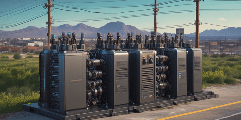
ETOS Hardware Modules
- ETOS systems are customized and manufactured in Regensburg, Germany to meet specific customer requirements.
- Each system consists of various hardware modules chosen to fulfill customer needs.
CPU Module
- The CPU module is the central component of ETOS, storing software and data.
- It provides multiple interfaces for connecting to customer SCADA systems or visualization tools.
- There are two CPU versions: CPU1 and CPU2, selected based on system complexity.
UI Modules
- ETOS has three UI modules: UI1, UI3, and UI5, each with distinct functionalities.
- UI1 and UI3 are used for standard applications, monitoring voltage and current.
- UI5 is required for advanced applications, specifically for monitoring torque and bushing.
Digital Input/Output (DIO) Modules
- ETOS offers two DIO module versions: 4220 and 2815.
- The 4220 module features 42 digital input contacts and 20 outputs.
- The 2815 module is a more compact alternative to the 4220.
AIO Cards
- AIO cards are available in two-channel and four-channel versions.
- These cards enable connection of common temperature sensors, such as PT100 and PT1000.
- They also allow input and output of 4-20 milliamp signals.
VI Card
- The VI card is necessary for enabling vibro-acoustic monitoring in ETOS.
- It supports connection of up to three Weber acoustic sensors to monitor tap changer noises.
SW-33 Redundancy Network Switch
- The SW-33 card is a redundancy network switch, allowing ETOS integration into a customer's redundant network system.
Backplane
- The backplane is a mounting plate for installing various ETOS modules.
- It is available in different sizes to accommodate customer-specific requirements.
ETOS Visualization
- ETOS visualization is a web-based application, running on HTML5, and does not require any additional software.
- It is compatible with all common browsers and runs smoothly.
Home Screen
- The home screen consists of four main parts.
- The functional section is at the center, featuring a pictogram of the transformer, and displays various values at a glance, including alarm statuses, temperatures, power meters, and more.
Navigation Bar
- The main navigation bar is located at the top of the screen and has two functions.
- It holds communication settings, such as IP addresses for SCADA communication.
- It serves as a tree structure, showing the user's current location and how to navigate back to previous menus.
Menu Bar
- The main menu bar is located on the right side of the screen and remains available at all times.
- It provides access to various sections, including information, parameters, and settings.
Administrative Bar
- The administrative bar is located at the bottom of the screen.
- It features language selection.
- It has active user management, with full user rights management.
- It has a reboot option, with a color indicator (red or black) to indicate when a reboot is necessary for certain parameters to take effect.
- It displays current user and date/time information.
- It has a tiny MR logo that, when clicked, opens a manual for the unit from the browser, without requiring an internet connection.
Import and Export Manager of ETOS
- Enables users to download data from the device and import it into their system, and transfer data from the system back to ETOS, which is useful for software updates.
- Accessed through the settings and export window.
File Types and Functions
- System Image: a comprehensive file that includes the device's history, settings, and historic data, downloadable with the logic editor included.
- CSV files: used for documentation, containing settings for a specific unit, such as a parameter list.
- Event Memory: a file that records all events that have occurred on the system.
- Event List: a comprehensive list of all possible events on ETOS.
- ZIP files: contain PDF files and other documents, such as operating instructions or SCADA configuration.
Settings.RHI File
- A practical file for transferring settings between units or keeping them as a backup.
- Allows settings to be transferred between units without restrictions.
Importing Files
- Files can be imported from a USB flash drive or local computer.
- Software imports are restricted to the proper unit based on the ETOS unit's serial number.
- SCADA-related files can be modified and re-imported.
- The software checks for compatibility during the import process.
Software Update of ETOS
- A software update on ETOS can be performed using a laptop computer, a standard Ethernet cable, and an update file stored on a USB flash drive.
Update Process
- The update process involves selecting the update file on the "Import" screen, which checks the device's serial number to ensure the update is valid.
- The process checks for historic data and programs in the logic editor of ETAS, which can be skipped if not applicable.
- The "Retain Settings" screen allows users to choose which settings to keep on the device, including user settings and device settings.
Important Considerations
- It is crucial to maintain a stable power supply to ETOS during the software update to prevent device malfunction.
- Hardware modifications required due to the software update can be carried out after the initial update process, and the device can be safely disconnected and reconnected.
Verification
- After the update, the device will automatically reboot.
- The user can verify the new software version in the "Information" > "System Software" menu.
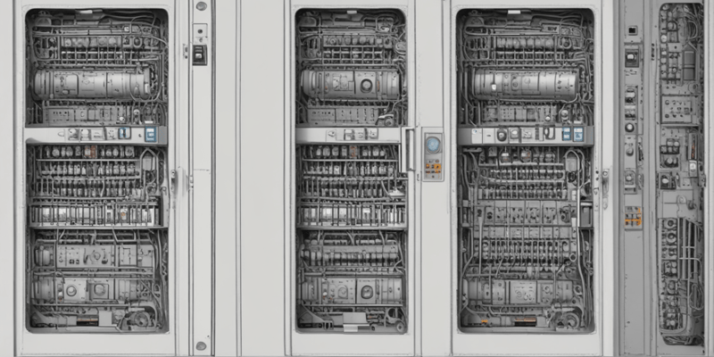
Wiring Diagram of Heatos
- Each unit has a unique wiring diagram, accessible on board or digitally through a QR code.
- The wiring diagram provides a comprehensive overview of the system, specifying installed components.
Components of the System
- The front panel consists of the control panel, CPU, and measurement cards for analog signals or voltage signals.
- Measurement cards include: • UI 3 for voltage and current measurement of the network situation • Motor measurement cards for torque monitoring
- Digital input/output contacts feature: • Digital input contacts for breakers, relays, and control signals (local or remote) • Freely configurable input contacts for various signals • Output contacts for: • Raise and lower signals for AVR function • Control status contacts • Cooling system signals (if included) • Freely configurable signals
Analog Signals and Sensors
- Analog signals are typically displayed in the lower section of each page.
- Example sensor connections: • Displaying devices driven by 4-20 mA or 0-10V signals (e.g., for tap position or actual voltage level) • Input from sensors delivering a 4-20 mA signal (e.g., oil level indicator) • pt100 or pt1000 sensors can be connected in 2-, 3-, or 4-wire mode.
Flexible DIO Configuration in Ethos
- Flexible DIO configuration allows users to customize digital input and output signals according to their requirements.
- This feature also applies to analog signals, but will be covered later.
DIO Configuration Section
- To access the DIO configuration section, users go to the settings on the Ethos home screen.
- The DIO configuration section displays a list of available signals on the unit, which can be extensive depending on the system's complexity.
Understanding the DIO Configuration Table
- The table has five columns: Function, Signal Type, Configuration, Assembly, and Channel.
- The Function column indicates whether a signal is an input (marked with "I") or an output (marked with "O").
- The Signal Type column shows whether signals come from/go to the DIO card or are part of the Modbus protocol.
- The Configuration column specifies whether an electric signal is high or low active.
- The Assembly and Channel columns enable users to modify the channel or assembly associated with a signal without disconnecting/reconnecting wires.
Customizing Signals
- Some signals are pre-configured based on the system's ordered functions.
- Other signals, such as binary inputs and outputs, are freely available for customization.
- Users can rename and configure these free signals as needed.
Ethos AIO Configuration
- Ethos AIO configuration allows for flexible configuration of analog signals and can be accessed from the home screen settings.
Analog Signal Configuration
- The configuration lists available functions, including inputs and outputs, with their respective units.
- Supported signal types include:
- 0 to 20 milliamp signals
- 4 to 20 milliamp signals
- 0 to 10 volt signals
- PT100, PT1000 in 2, 3, or 4 wire configurations
- Modbus signals
Channel Configuration
- The channel column selects the physical card and channel for signal connection.
- The gearbox icon enables further configuration, including:
- Signal scaling (e.g., 4 milliamps to -40°C, 20 milliamps to 150°C)
- Adding a correction factor and correction offset to fine-tune the signal
General Purpose Analog Signals
- General Purpose Analog In (GPAI) and General Purpose Analog Out (GPAO) signals can be configured.
- GPAI and GPAO signals can be linked to a free channel and configured with a specific unit from a long list of common physical units (e.g., bar, psi for pressure).
- Configuration options include selecting a multiplier (e.g., milli, kilo, mega) and decimal places.
Event Screen
- Displays all pending events on Ethos, categorized into three types: alarms (red), warnings (yellow), and information (gray).
- Each event has a unique event number and a full timestamp.
- Allows users to change the status and designation of events, including changing names and colors.
Event Log
- A historic list of all events that have occurred, organized by general function (e.g., drive, cabinet, cooling, etc.).
Filtering and Exporting Event Log
- Can be filtered by time period, event type, and other criteria.
- Allows users to export the filtered event log or the entire event log from the settings.
Recorder
- Displays a list of historic measured values, including:
- Gas values from DGA sensors
- Voltage and current measurements
- Bushing monitoring
- Users can select a specific time range and view the corresponding measured values.
- Allows for zooming and trending functions to analyze the data further.
- Enables users to export the data for further analysis.
Common Mistakes in Handling Etheros
Encryption
- Enable SSL/TLS encryption during commissioning or in the communications tab to ensure secure access
- Always use https in the address line to access the system after encryption is enabled
Dio Connection Cable
- Securely connect the purple cable between the CPU and Dio modules to prevent error stage and LED changes
- Power down the system, reconnect and tighten the cable, and then power up again to resolve connection issues
Ethernet Connection
- Use eth 2.1 port on the CPU module for communication to avoid issues
- Verify the correct port to ensure proper communication
Dio Module Power Supply
- Connect and power up the Dio module's power supply unit to ensure proper operation
- Check the power supply unit's LED for indication of proper operation
Event Confirmation
- Acknowledge or confirm events as required on the event screen to prevent system issues
- Regularly check the event screen for events requiring acknowledgment or confirmation
Visualization Issues
- Clear browser cache to resolve strange visualization issues and prevent future occurrences
- Regularly clearing cache can prevent visualization issues from arising
Configuration and Expansion
- Install cards card by card or slot by slot as per the electrical diagram when expanding the system
- Avoid mixing up slots or rotating cards to prevent startup errors during system expansion
Serialization and Unit Identification
- Verify the serial number of the unit matches the software being imported to avoid error messages
- Check the serial number before importing software to ensure compatibility
Canvas Communication Cards
- Use connectors with built-in resistors for cable termination in some units to prevent communication issues
- Ensure correct positioning of connectors to prevent communication issues
IP Address Configuration
- Change the local IP address of the computer or ethernet adapter to match the unit's IP range (192.168.165.x) for proper access
- Set the IP address to access the unit properly and avoid connection issues
Studying That Suits You
Use AI to generate personalized quizzes and flashcards to suit your learning preferences.
Description
This quiz covers the steps to connect to ETOS, an open system for monitoring and digitalization of power transformers, for the first time. It requires a laptop and a network cable.