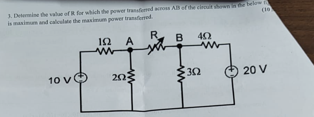
Determine the value of R for which the power transferred across AB of the circuit shown in the below figure is maximum and calculate the maximum power transferred.

Understand the Problem
The question is asking for the value of resistance R that enables maximum power transfer across points A and B in the given circuit. It also requests the calculation of this maximum power. This involves applying principles from circuit theory such as the maximum power transfer theorem.
Answer
The value of resistance \( R \) is approximately \( 2.22 \, \Omega \) and the maximum power transferred is approximately \( 3.66 \, W \).
Answer for screen readers
The value of resistance ( R ) for maximum power transfer is approximately ( 2.22 , \Omega ) and the maximum power transferred is approximately ( 3.66 , W ).
Steps to Solve
-
Identifying the Effective Resistance for Maximum Power Transfer To achieve maximum power transfer, the resistance $R$ must equal the Thevenin equivalent resistance ($R_{th}$) seen from the terminals A and B. We will first calculate $R_{th}$.
-
Finding the Thevenin Resistance To find $R_{th}$, we deactivate the independent voltage sources (replace 10V and 20V with short circuits) and find the equivalent resistance seen from terminals A and B.
The combination of resistors is as follows:
- The $2 , \Omega$ and $3 , \Omega$ resistors are in series.
- The equivalent resistance of $2 , \Omega$ and $3 , \Omega$ in series is: $$ R_{2,3} = 2, \Omega + 3, \Omega = 5, \Omega $$
- This $5 , \Omega$ is in parallel with the $4 , \Omega$ resistor: $$ R_{th} = \frac{R_{2,3} \cdot 4 , \Omega}{R_{2,3} + 4 , \Omega} = \frac{5 \cdot 4}{5 + 4} = \frac{20}{9} \approx 2.22, \Omega $$
-
Setting Up for Maximum Power Transfer For maximum power transfer, the resistance $R$ must equal $R_{th}$: $$ R = R_{th} \approx 2.22 , \Omega $$
-
Calculating Maximum Power Transferred Now, we find the maximum power transferred using the formula: $$ P_{max} = \frac{V_{th}^2}{4R_{th}} $$ We need to determine the Thevenin voltage ($V_{th}$) at terminals A and B with the independent sources active.
-
Calculating Thevenin Voltage The voltage across terminals A and B can be calculated using voltage division.
- The voltage seen at A can be found using the voltage divider: $$ V_{th} = 10V \cdot \frac{4, \Omega}{4, \Omega + 3, \Omega} = 10V \cdot \frac{4}{7} \approx 5.71 , V $$
- Calculating Maximum Power Substituting into the power equation: $$ P_{max} = \frac{(5.71)^2}{4 \cdot (2.22)} \approx \frac{32.55}{8.88} \approx 3.66 , W $$
The value of resistance ( R ) for maximum power transfer is approximately ( 2.22 , \Omega ) and the maximum power transferred is approximately ( 3.66 , W ).
More Information
This problem illustrates the maximum power transfer theorem, which states that to maximize power transfer from a source to a load, the load resistance should match the source's Thevenin resistance. The calculations involve basic circuit analysis techniques such as Thevenin equivalents and voltage division.
Tips
- Ignoring Voltage Sources: When finding Thevenin resistance, ensure to deactivate all independent voltage sources; failing to do so will yield incorrect results.
- Miscalculating Series and Parallel Combinations: Accurately calculating the equivalent resistance is crucial; mistakes often arise from wrong combinations.
AI-generated content may contain errors. Please verify critical information