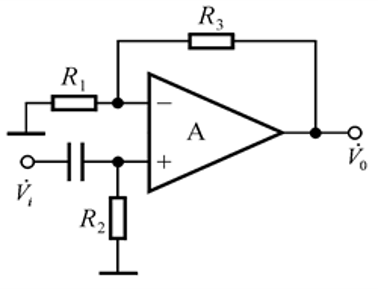
Determine the output voltage V₀ in terms of the input voltage Vᵢ and the resistances R₁, R₂, R₃.

Understand the Problem
The question appears to involve analyzing an electrical circuit with an operational amplifier. The aim is likely to determine the output voltage (V₀) based on the input voltage (Vᵢ) and the resistances (R₁, R₂, R₃).
Answer
The output voltage is given by the formula $V_0 = V_i \left(1 + \frac{R_3}{R_2}\right)$.
Answer for screen readers
The output voltage is given by the formula:
$$ V_0 = V_i \left(1 + \frac{R_3}{R_2}\right) $$
Steps to Solve
- Understand the circuit configuration
This circuit uses an operational amplifier (op-amp) in a non-inverting configuration. The relationship between the input voltage ($V_i$) and the output voltage ($V_0$) can be influenced by the resistors ($R_1$, $R_2$, and $R_3$).
- Applying the Non-Inverting Op-Amp Formula
For a non-inverting op-amp configuration, the output voltage can be calculated using the formula:
$$ V_0 = V_i \left(1 + \frac{R_3}{R_2}\right) $$
Where $R_2$ is the resistor connected to ground and $R_3$ is the feedback resistor.
- Relate the other resistor ($R_1$) if needed
If $R_1$ is used to set a reference voltage or in a different configuration, specify how it impacts the circuit. Depending on further conditions, if it’s in series or parallel with either of the resistors, you must account for its effect accordingly.
- Substituting values
If values for $V_i$, $R_2$, and $R_3$ are provided, plug them into the derived equation to find the output voltage.
The output voltage is given by the formula:
$$ V_0 = V_i \left(1 + \frac{R_3}{R_2}\right) $$
More Information
The formula for the output voltage of a non-inverting op-amp is fundamental in electronics and is widely used in signal amplification and processing. The gain of the op-amp can be adjusted by changing the resistances, making it versatile for different applications.
Tips
- Forgetting to include all resistors: Sometimes, the configuration may involve additional resistors that could change the gain significantly, so ensure to account for all relevant components.
- Confusing inverting and non-inverting configurations: Understand the distinction as the output relationships differ based on the configuration type.
AI-generated content may contain errors. Please verify critical information