What can you tell me about this electronic circuit diagram?

Understand the Problem
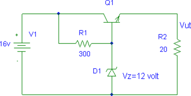
The question is asking about an electronic circuit diagram and likely seeks to understand how the components function together or how to analyze the circuit, including understanding the behavior of the transistor (Q1), resistor (R1), Zener diode (D1), and overall voltage output (Vout).
Answer
It's a Zener diode voltage regulator circuit for stabilizing voltage.
The electronic circuit diagram is a Zener diode voltage regulator circuit. It stabilizes output voltage (Vout) despite variations in input voltage or load current. V1 is a 16V DC power source. R1 limits current through D1, a 12V Zener diode, which stabilizes Vout. Q1 is a transistor handling the adjusted current to R2.
Answer for screen readers
The electronic circuit diagram is a Zener diode voltage regulator circuit. It stabilizes output voltage (Vout) despite variations in input voltage or load current. V1 is a 16V DC power source. R1 limits current through D1, a 12V Zener diode, which stabilizes Vout. Q1 is a transistor handling the adjusted current to R2.
More Information
Voltage regulators like this are used to ensure a stable output voltage for sensitive electronic devices, protecting them from fluctuations.
Tips
Common mistakes include not considering the power ratings of the components or misunderstanding the Zener diode's role, which can lead to circuit misbehavior.
Sources
- Understanding Circuit Diagrams - Components, Reading Guide and ... - byjus.com
- Learn Everything About Circuit Diagrams - SmartDraw - smartdraw.com
- How to Read a Schematic - SparkFun Learn - learn.sparkfun.com
AI-generated content may contain errors. Please verify critical information