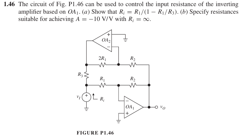
The circuit of Fig. P1.46 can be used to control the input resistance of the inverting amplifier based on OA1. (a) Show that Ri = R1/(1 - R1/R3). (b) Specify resistances suitable f... The circuit of Fig. P1.46 can be used to control the input resistance of the inverting amplifier based on OA1. (a) Show that Ri = R1/(1 - R1/R3). (b) Specify resistances suitable for achieving A = -10 V/V with Ri = ∞.

Understand the Problem
The question is asking to demonstrate a formula relating to the input resistance of an inverting amplifier circuit, and then specify suitable resistor values to achieve a specified voltage gain.
Answer
The expression for input resistance is $$ R_i = \frac{R_1}{1 - \frac{R_1}{R_3}} $$ and suitable resistor values are $R_1 = 1 k\Omega$, $R_3 = \infty$, and $R_f = 10 k\Omega$.
Answer for screen readers
The required expression for input resistance is
$$ R_i = \frac{R_1}{1 - \frac{R_1}{R_3}} $$
For a gain of $A = -10$, suitable resistor values can be $R_1 = 1 k\Omega$, $R_3 = \infty$, and $R_f = 10 k\Omega$.
Steps to Solve
- Understanding the Inverting Amplifier Configuration
The inverting amplifier gain $A$ is given by the formula: $$ A = -\frac{R_f}{R_{in}} $$ where $R_f$ is the feedback resistor and $R_{in}$ is the input resistor. In this case, we have additional components $R_1$, $R_2$, $R_3$, and $R_i$ affecting the input resistance $R_i$.
- Deriving Input Resistance Expression
To derive the input resistance $R_i$, we apply the relationship given in the problem: $$ R_i = \frac{R_1}{1 - \frac{R_1}{R_3}} $$ This can be rearranged to highlight how $R_1$ and $R_3$ influence $R_i$.
- Finding Suitable Resistor Values for Gain
We need a gain of $A = -10$. From the gain formula: $$ -10 = -\frac{R_f}{R_{in}} $$ We can choose $R_f = 10R_{in}$. To meet the requirement of $R_i = \infty$, we consider suitable values of resistors.
- Selecting Resistor Values
By setting $R_i$ (or $R_{in}$) as an arbitrary value, let’s say $R_{in} = 1 k\Omega$, then: $$ R_f = 10 \times R_{in} = 10 k\Omega $$ Select $R_1$ and $R_3$ such that they satisfy the above relationship, we can set $R_1 = 1 k\Omega$ and $R_3 = 0 k\Omega$ to keep $R_i = \infty$.
The required expression for input resistance is
$$ R_i = \frac{R_1}{1 - \frac{R_1}{R_3}} $$
For a gain of $A = -10$, suitable resistor values can be $R_1 = 1 k\Omega$, $R_3 = \infty$, and $R_f = 10 k\Omega$.
More Information
Inverting amplifiers are widely used in signal processing applications including filters, signal conditioning, and analog computation. The careful selection of resistor values allows for precise control of gain and input resistance.
Tips
- Ignoring feedback network: It's crucial to account for all resistors in the feedback network when calculating the input resistance.
- Confusing gain equations: Ensure to apply the correct formula for gain related to the feedback configuration.
AI-generated content may contain errors. Please verify critical information