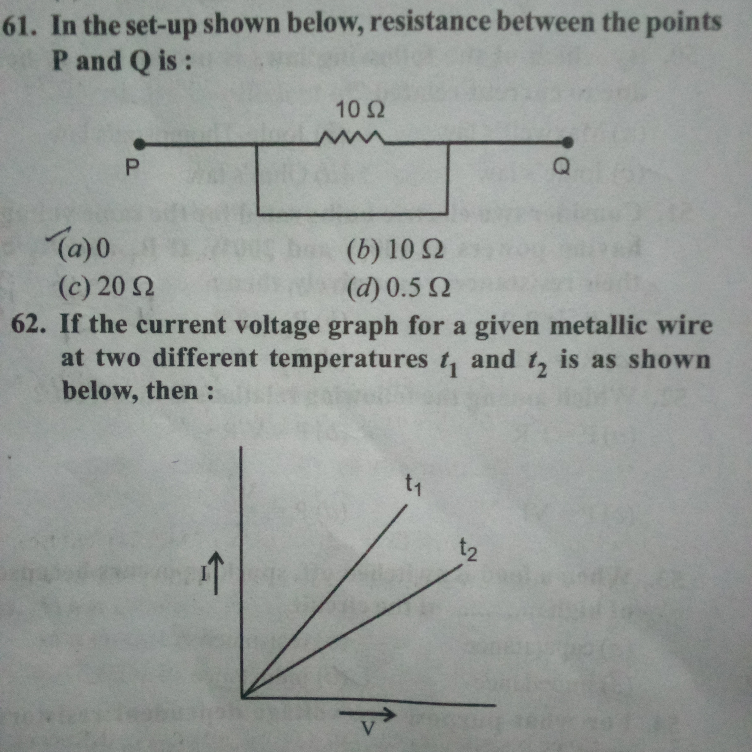
In the setup shown below, resistance between the points P and Q is: If the current voltage graph for a given metallic wire at two different temperatures t1 and t2 is as shown below... In the setup shown below, resistance between the points P and Q is: If the current voltage graph for a given metallic wire at two different temperatures t1 and t2 is as shown below, then:

Understand the Problem
The question is asking for the equivalent resistance between two points in a circuit and involves analyzing a current-voltage graph at different temperatures for a metallic wire. This involves concepts from electrical resistance and circuit analysis.
Answer
The equivalent resistance between points P and Q is \( 10 \, \Omega \).
Answer for screen readers
The equivalent resistance between points P and Q is ( 10 , \Omega ).
Steps to Solve
- Identify the circuit configuration
The circuit shown consists of a single 10 Ω resistor connected between two points, P and Q. Since this is a series circuit with only one resistor, the equivalent resistance is simply the resistance of that resistor.
- Calculate the equivalent resistance
In a simple series circuit, the resistance between two points is equal to the resistance of the resistor placed between them. Therefore, the equivalent resistance ( R_{eq} ) between points P and Q can be expressed as:
$$ R_{eq} = R = 10 , \Omega $$
- Analyze the current-voltage graph
The graph indicates different slopes at temperatures ( t_1 ) and ( t_2 ). The slope of the current-voltage graph (I-V graph) represents the resistance of the material. The steeper the slope, the lower the resistance. This means that at temperature ( t_1 ), let's denote the resistance as ( R_1 ), and at ( t_2 ), we denote the resistance as ( R_2 ).
- Determine the relationship between temperatures and resistance
In metals, resistance generally increases with temperature. Therefore, if ( R_1 < R_2 ), it implies that at ( t_1 ) (lower temperature), the resistance is less than at ( t_2 ) (higher temperature).
- Confirm the equivalent resistance conclusion
The equivalent resistance ( R_{eq} ) between points P and Q remains:
$$ R_{eq} = 10 , \Omega $$
This confirms the only resistance in the circuit.
The equivalent resistance between points P and Q is ( 10 , \Omega ).
More Information
The resistance value of ( 10 , \Omega ) directly reflects the single resistor present in the circuit, regardless of the conditions given in the current-voltage graph. The graph illustrates the behavior of the wire's resistance under varying temperatures, but does not alter the resistance between points P and Q.
Tips
- Confusing the properties of series and parallel circuits. Here, it's essential to recognize that only a single resistor is present; thus, the equivalent resistance is straightforward.
- Misinterpreting the slope of the I-V graph. Remember that the slope indicates resistance; a steeper slope signifies lower resistance.
AI-generated content may contain errors. Please verify critical information