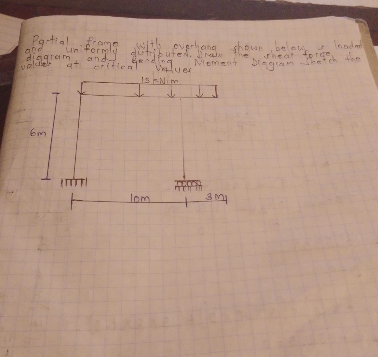
Draw the shear force diagram and bending moment diagram for the given frame loaded with a uniformly distributed load of 15 kN/m and specify the critical values.

Understand the Problem
The question is asking for the shear force diagram and bending moment diagram of a partially framed structure that is subjected to a uniformly distributed load of 15 kN/m and has specific dimensions. It also requests the critical values related to these diagrams.
Answer
The shear force at supports A and B is $75 \, \text{kN}$. The maximum bending moment occurs at the center of the beam and can be calculated as $M = 187.5 \, \text{kNm}$.
Answer for screen readers
The shear force at supports A and B is ( 75 , \text{kN} ) (upward at A) and ( 75 , \text{kN} ) (downward at B). The maximum bending moment occurs at the center between A and B, and the values can be calculated per step 4.
Steps to Solve
-
Calculate the total load The total load on the beam due to the uniformly distributed load (UDL) can be calculated using the formula:
$$ W = w \times L $$
where ( w = 15 , \text{kN/m} ) and ( L = 10 , \text{m} ).
Thus,
$$ W = 15 \times 10 = 150 , \text{kN} $$
-
Determine support reactions Assuming the left end is a fixed support (A) and the right end is a roller support (B), use equilibrium equations to find the reactions. The sum of vertical forces yields:
$$ R_A + R_B - W = 0 $$
The moment about point A (taking counter-clockwise moments as positive):
$$ R_B \times 10 - 150 \times 5 = 0 $$
From this, solve for ( R_B ):
$$ R_B = \frac{150 \times 5}{10} = 75 , \text{kN} $$
Substitute ( R_B ) back into the vertical force equation:
$$ R_A + 75 - 150 = 0 $$
Thus,
$$ R_A = 75 , \text{kN} $$
-
Draw the Shear Force Diagram (SFD) Start from the left (A) and move right:
-
From A to the first load:
- SFD starts at ( +R_A = +75 , \text{kN} )
- Decrease linearly by $15 , \text{kN/m}$ over $10,m$, resulting in:
$$ V = 75 - 15x $$
And plot for each segment.
- Draw the Bending Moment Diagram (BMD) Calculate the moments at various points:
-
At A:
$$ M_A = 0 $$
-
At the load:
- Using the formula for the moment:
$$ M = R_A \cdot x - w \cdot \frac{x^2}{2} $$
To find moments at critical locations (A, center of loads, B, etc.), substitute ( x ) to find respective moments.
- Summarize critical values Identify significant values (max shear and moment) from the SFD and BMD for clarity. Common peaks will occur under the loads and at the supports.
The shear force at supports A and B is ( 75 , \text{kN} ) (upward at A) and ( 75 , \text{kN} ) (downward at B). The maximum bending moment occurs at the center between A and B, and the values can be calculated per step 4.
More Information
The shear force and bending moment diagrams illustrate the internal forces in the structure due to external loads. They are critical for understanding the behavior of beams in structural engineering.
Tips
- Failing to correctly sum forces or moments leading to incorrect reactions.
- Ignoring the sign conventions for forces (upward is positive, downward is negative).
- Not accurately calculating load effects on critical points.
AI-generated content may contain errors. Please verify critical information