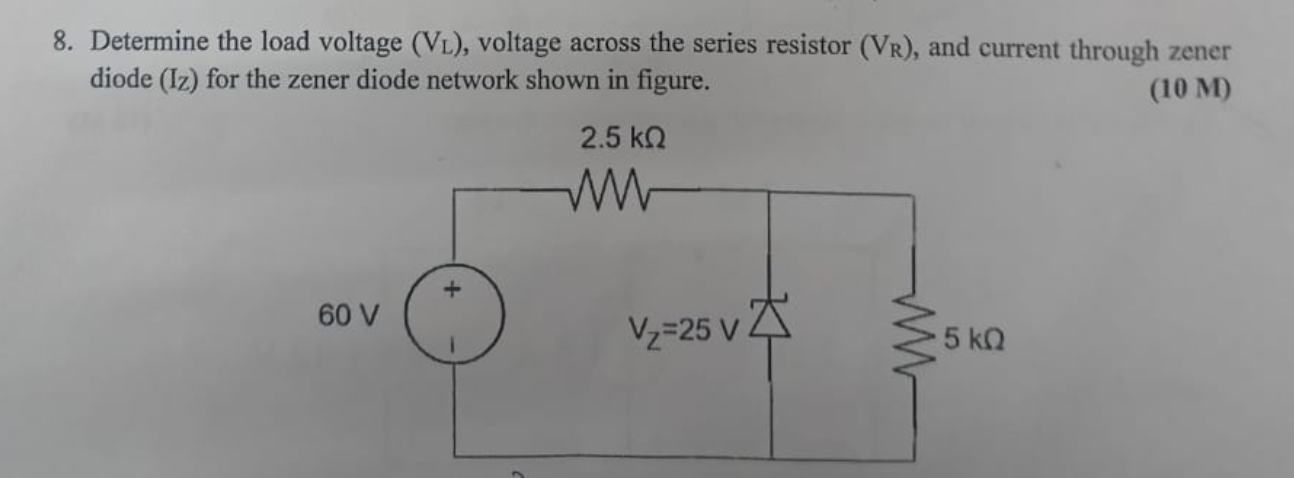
Determine the load voltage (VL), voltage across the series resistor (VR), and current through zener diode (IZ) for the zener diode network shown in figure.

Understand the Problem
The question is asking to calculate three electrical parameters in a zener diode circuit: the load voltage (VL), the voltage across the series resistor (VR), and the current through the zener diode (IZ). We will approach this by analyzing the circuit using Ohm's law and the properties of zener diodes.
Answer
Load Voltage: $V_L = 25\,V$, Voltage across Series Resistor: $V_R = 35\,V$, Current through Zener Diode: $I_Z = 9\,mA$
Answer for screen readers
- Load Voltage, $V_L = 25,V$
- Voltage across Series Resistor, $V_R = 35,V$
- Current through Zener Diode, $I_Z = 9,mA$
Steps to Solve
- Identify Circuit Parameters Identify the values given in the circuit:
- Input voltage, $V_{in} = 60,V$
- Zener voltage, $V_{Z} = 25,V$
- Series resistor, $R_{S} = 2.5,k\Omega$
- Load resistor, $R_{L} = 5,k\Omega$
-
Calculate Load Voltage (VL) In Zener diode circuits, the load voltage ($V_L$) is equal to the Zener voltage when the Zener is in regulation. Thus: $$ V_L = V_Z = 25,V $$
-
Calculate Current Across Load Resistor (IL) Using Ohm's law to find the current through the load resistor ($I_L$): $$ I_L = \frac{V_L}{R_L} = \frac{25,V}{5,k\Omega} = 0.005,A = 5,mA $$
-
Calculate Voltage Across Series Resistor (VR) Calculate the voltage across the series resistor ($V_R$) using: $$ V_R = V_{in} - V_L = 60,V - 25,V = 35,V $$
-
Calculate Current Through Series Resistor (IT) Using Ohm's law, calculate the current through the series resistor ($I_T$): $$ I_T = \frac{V_R}{R_S} = \frac{35,V}{2.5,k\Omega} = 0.014,A = 14,mA $$
-
Calculate Current Through Zener Diode (IZ) Determine the current through the Zener diode ($I_Z$) using the relationship: $$ I_Z = I_T - I_L = 14,mA - 5,mA = 9,mA $$
- Load Voltage, $V_L = 25,V$
- Voltage across Series Resistor, $V_R = 35,V$
- Current through Zener Diode, $I_Z = 9,mA$
More Information
In Zener diode circuits, the Zener maintains a constant voltage across the load until the current through the Zener diode exceeds its maximum limit. This ensures stable operation in various load conditions. The values calculated indicate a well-designed circuit for maintaining voltage.
Tips
- Forgetting to subtract $V_L$ from $V_{in}$ when calculating $V_R$.
- Confusing the direction of currents when determining $I_Z$; ensure clarity in understanding circuit flow.
- Not verifying if the Zener is in regulation at the calculated $V_L$.
AI-generated content may contain errors. Please verify critical information