Analyze the given logic circuit diagram and explain its functionality.
Understand the Problem
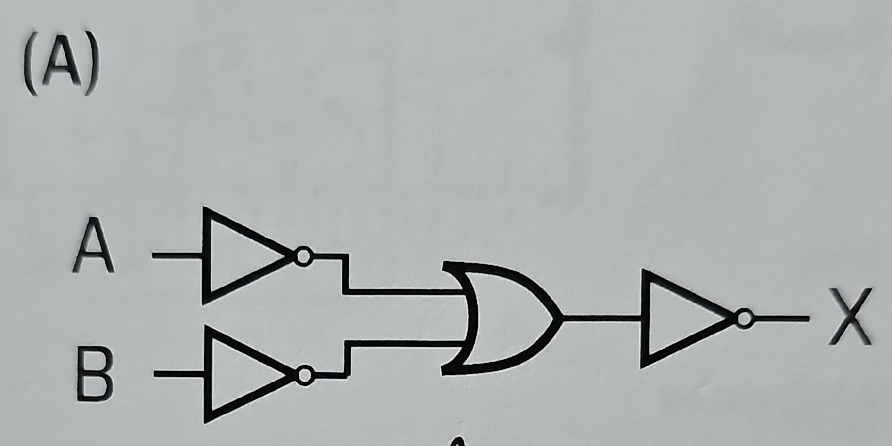
The question seems to be asking for an analysis or understanding of a logic circuit diagram that includes NOT and OR gates. It likely seeks an explanation of the function or the resultant output when given certain inputs A and B.
Answer
The circuit outputs the NOR of inputs A and B.
The circuit's functionality can be described as follows: NOT A and NOT B are inputs to an OR gate, whose output serves as an input to a final NOT gate. The final output is the NOR of A and B.
Answer for screen readers
The circuit's functionality can be described as follows: NOT A and NOT B are inputs to an OR gate, whose output serves as an input to a final NOT gate. The final output is the NOR of A and B.
More Information
A NOR gate combines the functionalities of NOT and OR gates, resulting in an output that is true only when all inputs are false.
Tips
One common mistake is misidentifying the gates or their operation. Ensure that you recognize the symbols correctly and understand the behavior of each type of gate.
Sources
- Combinational Logic Circuits using Logic Gates - Electronics Tutorials - electronics-tutorials.ws
- Basic Logic Gates - Types, Functions, Truth Table and ... - BYJU'S - byjus.com
AI-generated content may contain errors. Please verify critical information