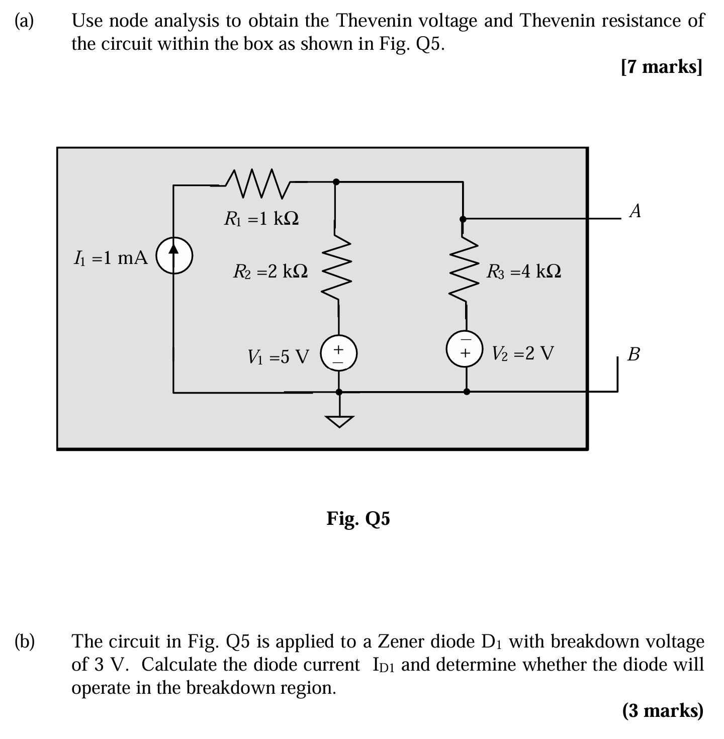
a) Use node analysis to obtain the Thevenin voltage and Thevenin resistance of the circuit within the box as shown in Fig. Q5. b) The circuit in Fig. Q5 is applied to a Zener diode... a) Use node analysis to obtain the Thevenin voltage and Thevenin resistance of the circuit within the box as shown in Fig. Q5. b) The circuit in Fig. Q5 is applied to a Zener diode D₁ with breakdown voltage of 3 V. Calculate the diode current ID1 and determine whether the diode will operate in the breakdown region.
Understand the Problem
The question consists of two parts related to circuit analysis. Part (a) requires using nodal analysis to determine the Thevenin voltage and Thevenin resistance of a circuit. Part (b) involves applying the circuit from part (a) to a Zener diode and calculating the diode current to determine if it operates in the breakdown region.
Answer
(a) $V_{TH} = \frac{8}{3} \text{V}$, $R_{TH} = \frac{4000}{3} \Omega$ (b) $I_{D1} = 0 \text{A}$. The diode is not in breakdown.
Answer for screen readers
(a) Thevenin Voltage: $V_{TH} = \frac{8}{3} \text{V} \approx 2.67 \text{V}$
Thevenin Resistance: $R_{TH} = \frac{4000}{3} \Omega \approx 1.33 \text{k}\Omega$
(b) Diode Current: $I_{D1} = 0 \text{A}$
The diode will not operate in the breakdown region.
Steps to Solve
- Find the Thevenin Voltage ($V_{TH}$)
First, we need to determine the Thevenin voltage by finding the open-circuit voltage between terminals A and B. We will use nodal analysis.
Let's define a node voltage $V_A$ at terminal A (relative to ground). Applying Kirchhoff's Current Law (KCL) at node A:
$$ \frac{V_A - V_1}{R_2} + \frac{V_A - V_2}{R_3} + I_1 = 0 $$
Given values: $I_1 = 1 \text{mA} = 0.001 \text{A}$, $R_1 = 1 \text{k}\Omega = 1000 \Omega$, $R_2 = 2 \text{k}\Omega = 2000 \Omega$, $R_3 = 4 \text{k}\Omega = 4000 \Omega$, $V_1 = 5 \text{V}$, $V_2 = 2 \text{V}$
Substituting the values into the equation:
$$ \frac{V_A - 5}{2000} + \frac{V_A - 2}{4000} + 0.001 = 0 $$
Multiplying through by 4000 to clear fractions:
$$ 2(V_A - 5) + (V_A - 2) + 4 = 0 $$
$$ 2V_A - 10 + V_A - 2 + 4 = 0 $$
$$ 3V_A - 8 = 0 $$
$$ 3V_A = 8 $$
$$ V_A = \frac{8}{3} \text{V} $$
Therefore, the Thevenin voltage $V_{TH} = V_A = \frac{8}{3} \text{V} \approx 2.67 \text{V}$.
- Find the Thevenin Resistance ($R_{TH}$)
To find the Thevenin resistance, we need to deactivate the independent sources. This means replacing the voltage sources with short circuits and the current source with an open circuit. Looking back into the terminals A and B, we see $R_2$ and $R_3$ are in parallel. This parallel combination is then in series with $R_1$, but $R_1$ is shorted by the current source being open. Thus, the Thevenin resistance is just the parallel combination of $R_2$ and $R_3$.
$$ R_{TH} = \frac{R_2 \cdot R_3}{R_2 + R_3} $$
$$ R_{TH} = \frac{2000 \cdot 4000}{2000 + 4000} = \frac{8000000}{6000} = \frac{4000}{3} \Omega $$
Therefore, the Thevenin resistance $R_{TH} = \frac{4000}{3} \Omega \approx 1.33 \text{k}\Omega$.
- Analyze the Zener Diode Circuit
Now, we connect a Zener diode with a breakdown voltage of 3V to the Thevenin equivalent circuit. The Thevenin equivalent circuit consists of a voltage source $V_{TH}$ in series with a resistor $R_{TH}$.
To determine if the Zener diode is in breakdown, we need to see if the voltage across it would exceed its breakdown voltage if it were not there. Since $V_{TH} = \frac{8}{3} \text{V} \approx 2.67 \text{V}$, which is less than the Zener breakdown voltage of 3V, the diode is NOT in breakdown.
Since the Zener diode is not in breakdown, it acts virtually as an open circuit. Therefore, the current through the diode, $I_{D1} = 0 \text{A}$.
(a) Thevenin Voltage: $V_{TH} = \frac{8}{3} \text{V} \approx 2.67 \text{V}$
Thevenin Resistance: $R_{TH} = \frac{4000}{3} \Omega \approx 1.33 \text{k}\Omega$
(b) Diode Current: $I_{D1} = 0 \text{A}$
The diode will not operate in the breakdown region.
More Information
The Thevenin equivalent is a powerful tool for simplifying circuits. It allows us to replace a complex circuit with a simple voltage source and resistor, making it easier to analyze the behavior of the circuit when connected to a load, such as the Zener diode in this problem. Zener diodes are designed to operate in the breakdown region, providing a stable voltage reference.
Tips
-
Incorrect Nodal Analysis: A common mistake is to incorrectly apply KCL at the node, especially regarding the direction of currents and the signs of voltages when using the formula $\frac{V_1 - V_2}{R}$.
-
Incorrect $R_{TH}$ Calculation: Forgetting to deactivate the sources when calculating $R_{TH}$ is a frequent error. Also, misidentifying the series and parallel combinations of resistors after deactivation can lead to an incorrect $R_{TH}$ value.
-
Zener Diode Misunderstanding: Assuming the Zener diode always operates in breakdown is wrong. It only operates in breakdown if the voltage across it (in the reverse direction) equals or exceeds its breakdown voltage ($V_Z$). Confusing the polarity of the Zener diode is a common error as well.
AI-generated content may contain errors. Please verify critical information