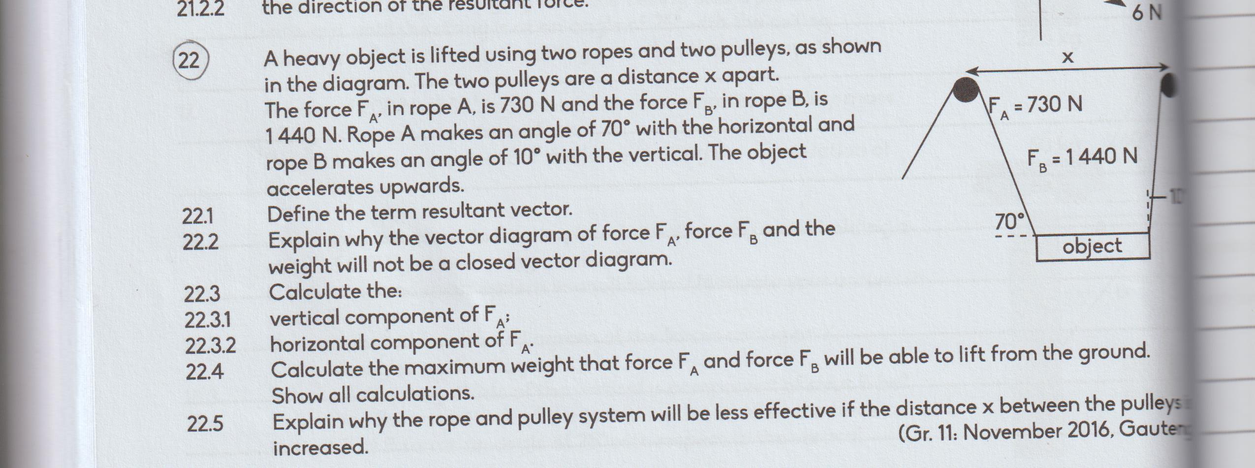
A heavy object is lifted using two ropes and two pulleys, as shown in the diagram. The force F_A in rope A is 730 N and the force F_B in rope B is 1440 N. Rope A makes an angle of... A heavy object is lifted using two ropes and two pulleys, as shown in the diagram. The force F_A in rope A is 730 N and the force F_B in rope B is 1440 N. Rope A makes an angle of 70° with the horizontal and rope B makes an angle of 10° with the vertical. The object accelerates upwards. 22.1 Define the term resultant vector. 22.2 Explain why the vector diagram of force F_A, force F_B and the weight will not be a closed vector diagram. 22.3 Calculate the vertical component of F_A; horizontal component of F_A; 22.4 Calculate the maximum weight that force F_A and force F_B will be able to lift from the ground. 22.5 Explain why the rope and pulley system will be less effective if the distance x between the pulleys is increased.
Understand the Problem
The question involves calculations related to forces acting on an object being lifted by two ropes at different angles. It asks for the definition of a resultant vector, an explanation of a vector diagram's properties, and to calculate the vertical and horizontal components of one force, as well as the maximum weight that can be lifted. Additionally, it requires an explanation of how the distance between pulleys affects the system's effectiveness.
Answer
The maximum weight that can be lifted is calculated using the formula: $$ W_{\text{max}} = 730 \sin(70^\circ) + 1440 \sin(10^\circ) $$
Answer for screen readers
The maximum weight that can be lifted is:
$$ W_{\text{max}} = F_{Ay} + F_{By} $$
Where:
$$ F_{Ay} = 730 \sin(70^\circ) $$
$$ F_{By} = 1440 \sin(10^\circ) $$
Steps to Solve
-
Define the Resultant Vector A resultant vector is a single vector that represents the combined effect of two or more individual vectors. It can be found by adding the individual vectors together, taking into account their directions.
-
Explain the Vector Diagram The vector diagram representing the forces $F_A$ and $F_B$ and the weight of the object will not be a closed vector diagram because the upward vectors (the forces) do not equal the downward vector (the weight) when the object accelerates upwards. This means that the sum of the forces is greater than the weight.
-
Calculate the Vertical Component of $F_A$ To find the vertical component of force $F_A$, we use trigonometry:
$$ F_{Ay} = F_A \sin(70^\circ) $$
Substituting in the value of $F_A$:
$$ F_{Ay} = 730 \sin(70^\circ) $$
- Calculate the Horizontal Component of $F_A$ To find the horizontal component of force $F_A$, apply:
$$ F_{Ax} = F_A \cos(70^\circ) $$
Again substituting in the value:
$$ F_{Ax} = 730 \cos(70^\circ) $$
- Calculate the Maximum Weight The maximum weight that can be lifted is the sum of the vertical components of both forces. The vertical component of force $F_B$ can be calculated similarly:
$$ F_{By} = F_B \sin(10^\circ) $$
Now sum the vertical components to find the maximum weight:
$$ W_{\text{max}} = F_{Ay} + F_{By} $$
- Explain the Effect of Distance Between Pulleys As the distance $x$ between the pulleys increases, the angles of the ropes become shallower. This results in a larger horizontal component and smaller vertical component for each rope, making it less effective at lifting the object.
The maximum weight that can be lifted is:
$$ W_{\text{max}} = F_{Ay} + F_{By} $$
Where:
$$ F_{Ay} = 730 \sin(70^\circ) $$
$$ F_{By} = 1440 \sin(10^\circ) $$
More Information
In this scenario, the inclusion of multiple pulleys can significantly change how forces act on the object being lifted. Understanding the direction and components of the forces applied by the ropes helps in determining how to effectively lift an object.
Tips
- Forgetting to use the correct angle for trigonometric functions.
- Ignoring the need to break down the forces into their vertical and horizontal components.
- Confusing angles between horizontal and vertical directions while calculating components.
AI-generated content may contain errors. Please verify critical information