Podcast
Questions and Answers
Signalling equipment must function normally despite the presence of traction current.
Signalling equipment must function normally despite the presence of traction current.
True (A)
No traction mast should be located less than 5 meters in advance of the signal post.
No traction mast should be located less than 5 meters in advance of the signal post.
False (B)
Electrostatic induction is completely eliminated when using overhead electified (OHE) structures.
Electrostatic induction is completely eliminated when using overhead electified (OHE) structures.
False (B)
The height of the centre line of the red signal should be approximately 3.65 meters above rail level.
The height of the centre line of the red signal should be approximately 3.65 meters above rail level.
Visibility of signals in AC electrified areas is solely dependent on the surrounding environment.
Visibility of signals in AC electrified areas is solely dependent on the surrounding environment.
Return current through rails and conductors can influence induced voltage levels.
Return current through rails and conductors can influence induced voltage levels.
Signals located between tracks can have OHE structures provided in the same track space within 600 meters in rear of the signals.
Signals located between tracks can have OHE structures provided in the same track space within 600 meters in rear of the signals.
Only traditional incandescent signals shall be utilized in electrified areas.
Only traditional incandescent signals shall be utilized in electrified areas.
Portal drop arms are allowed to be located within 600 meters before the signal as long as they do not infringe with the track schedule.
Portal drop arms are allowed to be located within 600 meters before the signal as long as they do not infringe with the track schedule.
The signal post should be lower than the OHE mast when positioned on tangent tracks.
The signal post should be lower than the OHE mast when positioned on tangent tracks.
Electrical clearances of signals in electrified areas should always be maintained without provision for protective measures.
Electrical clearances of signals in electrified areas should always be maintained without provision for protective measures.
The site for signals on curved tracks should be examined individually by a committee.
The site for signals on curved tracks should be examined individually by a committee.
Electro-magnetic induction causes varying currents and voltages in conductors parallel to the track.
Electro-magnetic induction causes varying currents and voltages in conductors parallel to the track.
The length of parallelism between cable conductors and electrified track has no effect on induced voltage.
The length of parallelism between cable conductors and electrified track has no effect on induced voltage.
The maximum height for a signal without a route indicator is 6.0 meters above rail level.
The maximum height for a signal without a route indicator is 6.0 meters above rail level.
Special studies must be conducted if a portal drop arm is located in rear of the signal itself.
Special studies must be conducted if a portal drop arm is located in rear of the signal itself.
The maximum permissible induced voltage for human safety is restricted to 600 V.
The maximum permissible induced voltage for human safety is restricted to 600 V.
The maximum length of direct feed of signal on a single track using unscreened cable is 180 m.
The maximum length of direct feed of signal on a single track using unscreened cable is 180 m.
Double track systems using unscreened cable can have a maximum length of 250 m.
Double track systems using unscreened cable can have a maximum length of 250 m.
Controlling relays must be located at the site when a signal exceeds the prescribed distance.
Controlling relays must be located at the site when a signal exceeds the prescribed distance.
Signal feed systems must operate at 60 Hz to align with regulations.
Signal feed systems must operate at 60 Hz to align with regulations.
The value of the factor of safety considered for the maximum permissible induced voltage is 2.0.
The value of the factor of safety considered for the maximum permissible induced voltage is 2.0.
The purpose of limiting the distance between signal control relays and the signal is to prevent illumination of lamps under adverse conditions.
The purpose of limiting the distance between signal control relays and the signal is to prevent illumination of lamps under adverse conditions.
All relay types listed can withstand an induced voltage below the maximum permissible limit.
All relay types listed can withstand an induced voltage below the maximum permissible limit.
If the distance between two insulators on the same rod exceeds 300 meters, additional insulators are not required.
If the distance between two insulators on the same rod exceeds 300 meters, additional insulators are not required.
The operating rod of locally worked points must have an insulator to ensure insulation from the rail.
The operating rod of locally worked points must have an insulator to ensure insulation from the rail.
The clearance between the insulator and the adjacent rod roller may be minimal and does not need to permit movement.
The clearance between the insulator and the adjacent rod roller may be minimal and does not need to permit movement.
When a rod crosses the track, it must maintain a minimum height of 40 mm from the bottom of the rail.
When a rod crosses the track, it must maintain a minimum height of 40 mm from the bottom of the rail.
All insulators in a run can be provided between different sets of rollers and guides.
All insulators in a run can be provided between different sets of rollers and guides.
Railway personnel do not need to take precautions when working near 25 KV A.C traction.
Railway personnel do not need to take precautions when working near 25 KV A.C traction.
The distance between any overhead equipment mast and the point rods should be at least 40 mm.
The distance between any overhead equipment mast and the point rods should be at least 40 mm.
Presence of return currents in the rails poses no risk to railway personnel.
Presence of return currents in the rails poses no risk to railway personnel.
The staff responsible for the operation of the Signalling equipment must check whether all signalling equipment is functioning normally.
The staff responsible for the operation of the Signalling equipment must check whether all signalling equipment is functioning normally.
If any equipment is found to be functioning abnormally, its operation can continue without immediate suspension.
If any equipment is found to be functioning abnormally, its operation can continue without immediate suspension.
An authorized representative must submit a Certificate after ensuring that everything is working correctly.
An authorized representative must submit a Certificate after ensuring that everything is working correctly.
The checklist for works to be completed is issued by the Chief Engineer of the Signal and Telecom department.
The checklist for works to be completed is issued by the Chief Engineer of the Signal and Telecom department.
Existing DC track relays must be replaced with AC immunized relays as part of the anti-theft measures.
Existing DC track relays must be replaced with AC immunized relays as part of the anti-theft measures.
A clearance certificate from DOT is not necessary prior to the 2.2 KV anti-theft energisation.
A clearance certificate from DOT is not necessary prior to the 2.2 KV anti-theft energisation.
The working clearance needed for signalling installations should be at least 2 meters from any live conductor.
The working clearance needed for signalling installations should be at least 2 meters from any live conductor.
Insulated tools must be provided to maintenance staff for safety during their work.
Insulated tools must be provided to maintenance staff for safety during their work.
The minimum height for masts before a signal without approach should be 3.25 m for distances beyond 400 m.
The minimum height for masts before a signal without approach should be 3.25 m for distances beyond 400 m.
Masts should ideally be placed in the same lane as signals for at least 600 m before a signal when signals do not have route indicators.
Masts should ideally be placed in the same lane as signals for at least 600 m before a signal when signals do not have route indicators.
The minimum setting of masts for colour light signals with horizontal route indicators varies based on distance ranges up to 310 m.
The minimum setting of masts for colour light signals with horizontal route indicators varies based on distance ranges up to 310 m.
The height of masts for signals other than distant signals starts at 3.25 m.
The height of masts for signals other than distant signals starts at 3.25 m.
For colour light signals without route indicators, the minimum setting of masts remains constant regardless of distance.
For colour light signals without route indicators, the minimum setting of masts remains constant regardless of distance.
Masts before signals with horizontal route indicators should have a minimum height of 2.75 m for distances up to 250 m.
Masts before signals with horizontal route indicators should have a minimum height of 2.75 m for distances up to 250 m.
When setting masts for colour light signals with route indicators, at least five different height settings are specified.
When setting masts for colour light signals with route indicators, at least five different height settings are specified.
The minimum height of masts for colour light signals located between tracks should always be 3.25 m.
The minimum height of masts for colour light signals located between tracks should always be 3.25 m.
Flashcards
Signaling Equipment Functionality in Electrified Areas
Signaling Equipment Functionality in Electrified Areas
The process of ensuring that signaling equipment continues to function even when electric traction currents are present.
Preventing Interference from Traction Systems
Preventing Interference from Traction Systems
The goal of preventing interference from the traction system from causing false indications or compromising train safety.
Electric Shock Hazard
Electric Shock Hazard
The potential for electric shock poses a significant safety hazard for equipment and personnel in electrified areas.
Signal Visibility in Electrified Areas
Signal Visibility in Electrified Areas
Signup and view all the flashcards
Electrical Clearances in Electrified Areas
Electrical Clearances in Electrified Areas
Signup and view all the flashcards
Traction Return Current
Traction Return Current
Signup and view all the flashcards
Electrostatic Induction
Electrostatic Induction
Signup and view all the flashcards
Electromagnetic Induction
Electromagnetic Induction
Signup and view all the flashcards
Signal Post and Traction Mast Spacing
Signal Post and Traction Mast Spacing
Signup and view all the flashcards
Reducing Signal Post and Traction Mast Distance
Reducing Signal Post and Traction Mast Distance
Signup and view all the flashcards
Signal Post Height
Signal Post Height
Signup and view all the flashcards
Signal Placement on Tangent Tracks
Signal Placement on Tangent Tracks
Signup and view all the flashcards
OHE Mast Placement near Signals
OHE Mast Placement near Signals
Signup and view all the flashcards
Signal Location on Curved Tracks or Obstructions
Signal Location on Curved Tracks or Obstructions
Signup and view all the flashcards
Signal Fittings and Track Dimensions
Signal Fittings and Track Dimensions
Signup and view all the flashcards
Signal Height Above Rail Level
Signal Height Above Rail Level
Signup and view all the flashcards
Maximum Permissible Induced Voltage
Maximum Permissible Induced Voltage
Signup and view all the flashcards
Feeding Distance
Feeding Distance
Signup and view all the flashcards
Signal Feed System
Signal Feed System
Signup and view all the flashcards
Maximum Permitted Length of Direct Feed (Single Track)
Maximum Permitted Length of Direct Feed (Single Track)
Signup and view all the flashcards
Maximum Permitted Length of Direct Feed (Double Track)
Maximum Permitted Length of Direct Feed (Double Track)
Signup and view all the flashcards
Locally Fed Signals
Locally Fed Signals
Signup and view all the flashcards
Remotely Fed Signals
Remotely Fed Signals
Signup and view all the flashcards
Typical Remote Feeding Circuit
Typical Remote Feeding Circuit
Signup and view all the flashcards
Insulator Spacing
Insulator Spacing
Signup and view all the flashcards
Electrical Isolation of Point Components
Electrical Isolation of Point Components
Signup and view all the flashcards
Insulator Placement for Rod Continuity
Insulator Placement for Rod Continuity
Signup and view all the flashcards
Clearance for Rod Movement
Clearance for Rod Movement
Signup and view all the flashcards
Rod Clearance Over Track
Rod Clearance Over Track
Signup and view all the flashcards
Insulator on Point Rod
Insulator on Point Rod
Signup and view all the flashcards
Safety Precautions for Railway Personnel
Safety Precautions for Railway Personnel
Signup and view all the flashcards
Mast Placement Near Signals
Mast Placement Near Signals
Signup and view all the flashcards
Mast Spacing with Horizontal Route Indicators
Mast Spacing with Horizontal Route Indicators
Signup and view all the flashcards
Mast Placement for Signals Between Tracks
Mast Placement for Signals Between Tracks
Signup and view all the flashcards
Mast Spacing for Signals without Route Indicators
Mast Spacing for Signals without Route Indicators
Signup and view all the flashcards
Mast Spacing for Signals with Other Route Indicators
Mast Spacing for Signals with Other Route Indicators
Signup and view all the flashcards
Reduced Mast Spacing
Reduced Mast Spacing
Signup and view all the flashcards
Signal Placement for Obstacles and Curves
Signal Placement for Obstacles and Curves
Signup and view all the flashcards
Study Notes
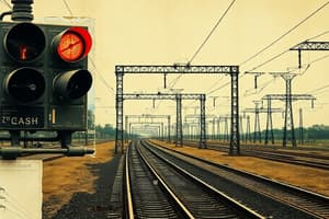
Signalling Requirements in 25 KV AC Electrified Areas
- Objectives: Ensure signalling equipment functions normally in the presence of traction current, prevent interference from traction systems that could imperil train safety, and protect personnel from electric shock.
Factors Affecting Signalling
-
Visibility: Proper OHE (Overhead Line Equipment) placement during design is crucial for signal visibility. Protective shields are necessary where electrical clearances can't be maintained. Signal layout plans must align with approved signalling plans. Protective wire-mesh screens are required in situations where clearances from live OHE conductors are more than 2 meters
-
Electrical Clearances: Electrical clearances of signals are needed because of live overhead line equipment.
-
Traction Return Current: This current can affect signal operation.
-
Electrostatic/Electromagnetic Induction: These factors influence signals by inducing currents and voltages in parallel conductors. Various factors like conductor parallelism, soil conductivity, cable screening, return current paths, mutual inductances, and current carried by the catenary affect the voltage.
Signal Structures in Electrified Areas
-
Colour Light Signals: Only colour light signals are used in electrified areas.
-
Signal Clearance Diagrams: Specific diagrams (Drg. No 22-D1, etc.) guide signal location and clearance from live parts of OHE based on tangent and curved track configurations with specific super-elevation values.
-
Signal Visibility: Signal locations must ensure visibility for train operators (Loco pilots). Signal sighting committees should verify visibility and make necessary adjustments.
Signal Circuits
-
Aerial Circuits: Avoid using aerial signalling circuits within electrified zones.
-
Earth Returns: Avoid using earth-return circuits in AC electrified areas.
-
Equipment Protection: Electrical signalling equipment that cannot safely withstand AC induced voltage should be used within designated locations, like cabin or internal circuit boxes,and have no external connections. Batteries and wire connections for such equipment must be well insulated from ground.
-
Relay Response (Interlocking): Relays that release interlocking should have a delay (0.6-0.8 seconds) to prevent inadvertent release from voltage fluctuations.
Outdoor Signalling Circuits
-
Parallelism: Maintain circuit lengths that ensure induced voltages from traction systems don't exceed 400 Volts. Sectionalization of line circuits may be required in some cases. Power supply is needed to prevent voltage limits
-
DC Circuits: Length limitations exist for DC circuits based on the type of relay, immunity level, and whether cables are screened.
-
Signal Feeding: Signal feed system should be 110V/50Hz. Maximum length for direct signal feeding is important and is determined in a table.
Point Operation
-
Electric/Mechanical Operation: Point operation might be electric or mechanical. Precautions are required when engaging the mechanism that operates points.
-
Length Restriction & Immunity: The length of electric point operation is restricted based on point machine type and immunity level.
Insulated Rod Joints
-
Insulators: Rod joints should have insulation provided in the lead-out portion, particularly close to the cabin, to prevent transmission of rail voltage and other hazards. Additional insulators are needed between certain sections, or if the distance is greater than 300 meters. Isolated points from tracks are essential.
-
Clearances: Maintained clearances between rail, insulators, rods, and other equipment parts are crucial to avoid electric shocks.
Staff Protection
-
Proximity to Live Conductors: Avoid contact with live conductors (25KV).
-
Return Current: Return currents in rails can create potential differences that are potentially hazardous, and require careful handling and attention.
-
Insulated Tools and Materials: Workers need to use insulated tools and materials for safety during maintenance/repair.
-
Safety Precautions: Specific procedures/rules apply when working on signalling equipment in electrified areas to protect workers from electric shock or other hazards.
Studying That Suits You
Use AI to generate personalized quizzes and flashcards to suit your learning preferences.
Related Documents
Description
This quiz explores the signaling requirements in electrified areas with 25 KV AC traction systems. Key aspects include ensuring safe operation of signaling equipment, preventing interference from traction systems, and understanding the factors affecting visibility and electrical clearances. Test your knowledge on these crucial topics for train safety.