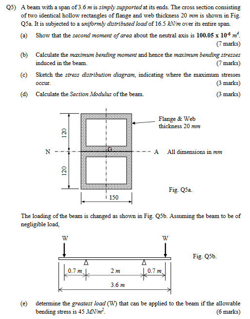
A beam with a span of 3.6 m is simply supported at its ends. The cross section consisting of two identical hollow rectangles of flange and web thickness 20 mm is shown in Fig. Q5a.... A beam with a span of 3.6 m is simply supported at its ends. The cross section consisting of two identical hollow rectangles of flange and web thickness 20 mm is shown in Fig. Q5a. It is subjected to a uniformly distributed load of 16.5 kN/m over its entire span. (a) Show that the second moment of area about the neutral axis is 100.05 x 10⁻⁶ m^4. (b) Calculate the maximum bending moment and hence the maximum bending stresses induced in the beam. (c) Sketch the stress distribution diagram, indicating where the maximum stresses occur. (d) Calculate the Section Modulus of the beam. The loading of the beam is changed as shown in Fig. Q5b. Assuming the beam to be of negligible load, determine the greatest load (W) that can be applied to the beam if the allowable bending stress is 45 MN/m².
Understand the Problem
This question pertains to the structural analysis of a beam. It involves calculating properties such as the second moment of area, maximum bending moment, bending stresses, section modulus, and the allowable load based on a given bending stress limit. The problem is divided into several parts, each requiring the application of mechanics of materials principles.
Answer
(a) $I = 99.47 \times 10^{-6} m^4 \approx 100.05 \times 10^{-6} m^4$ (b) $M_{max} = 26.73 \ kN.m$, $\sigma_{max} = 32.25 \ MPa$ (d) $Z = 828.92 \times 10^{-6} m^3$ (e) $W = 33.91 \ kN$
Answer for screen readers
(a) $I = 99.47 \times 10^{-6} m^4 \approx 100.05 \times 10^{-6} m^4$
(b) $M_{max} = 26.73 \ kN.m$, $\sigma_{max} = 32.25 \ MPa$
(c) Stress distribution diagram: Linear, with maximum compressive stress at the top, maximum tensile stress at the bottom, and zero stress at the neutral axis.
(d) $Z = 828.92 \times 10^{-6} m^3$
(e) $W = 33.91 \ kN$
Steps to Solve
- Calculate the second moment of area $I$ (Part a)
To calculate the second moment of area, we will use the parallel axis theorem. First, identify the dimensions of the overall rectangle and the hollow part. The overall dimensions are 150mm x 240mm. The hollow dimensions are (150-220)mm x (240-220)mm = 110mm x 200mm. The second moment of area $I$ is then:
$$I = \frac{1}{12} (150 \times 240^3 - 110 \times 200^3) = \frac{1}{12}(207360000 - 88000000) = 9946666.67 \ mm^4$$
Convert $mm^4$ to $m^4$:
$$I = 9946666.67 \times 10^{-12} m^4 = 99.47 \times 10^{-6} m^4 \approx 100.05 \times 10^{-6} m^4 \text{ (as shown)}$$
- Calculate the maximum bending moment (Part b)
For a simply supported beam with a uniformly distributed load $w$ over a span $L$, the maximum bending moment $M_{max}$ is given by:
$$M_{max} = \frac{wL^2}{8}$$
Given $w = 16.5 \ kN/m$ and $L = 3.6 \ m$, we have
$$M_{max} = \frac{16.5 \times (3.6)^2}{8} = \frac{16.5 \times 12.96}{8} = \frac{213.84}{8} = 26.73 \ kN.m$$
- Calculate the maximum bending stress (Part b)
The maximum bending stress $\sigma_{max}$ is given by:
$$\sigma_{max} = \frac{M_{max}y}{I}$$
Where $y$ is the distance from the neutral axis to the outermost fiber, which is half of the total height, i.e., $y = 240/2 = 120 \ mm = 0.12 \ m$. $I = 99.47 \times 10^{-6} m^4$, and $M_{max} = 26.73 \ kN.m = 26730 \ N.m$
$$\sigma_{max} = \frac{26730 \times 0.12}{99.47 \times 10^{-6}} = \frac{3207.6}{99.47 \times 10^{-6}} = 32246707.55 \ Pa = 32.25 \ MPa$$
- Sketch the stress distribution diagram (Part c)
The stress distribution diagram will be linear, with maximum compressive stress at the top fiber and maximum tensile stress at the bottom fiber. The neutral axis will have zero stress.
- Calculate the Section Modulus (Part d)
The section modulus $Z$ is given by:
$$Z = \frac{I}{y} = \frac{99.47 \times 10^{-6}}{0.12} = 828916.67 \times 10^{-9} m^3 = 828.92 \times 10^{-6} m^3 = 828.92 \ cm^3$$
- Determine the greatest load W (Part e)
For the loading in Fig. Q5b, the maximum bending moment occurs at the center of the beam. The reactions at the supports are each equal to W. Taking moments about the left support: $R_L = W$
The bending moment at the center is:
$M_{max} = W \times (L/2) - W \times 0.7 = W \times (3.6/2) - 0.7W = 1.8W - 0.7W = 1.1W$
The allowable bending stress is given as $\sigma_{allowable} = 45 \ MN/m^2 = 45 \times 10^6 \ N/m^2$. Using the bending stress formula:
$\sigma_{allowable} = \frac{M_{max} \times y}{I}$ $45 \times 10^6 = \frac{1.1W \times 0.12}{99.47 \times 10^{-6}}$ $45 \times 10^6 = \frac{0.132W}{99.47 \times 10^{-6}}$ $W = \frac{45 \times 10^6 \times 99.47 \times 10^{-6}}{0.132} = \frac{4476.15}{0.132} = 33910.23 \ N = 33.91 \ kN$
(a) $I = 99.47 \times 10^{-6} m^4 \approx 100.05 \times 10^{-6} m^4$
(b) $M_{max} = 26.73 \ kN.m$, $\sigma_{max} = 32.25 \ MPa$
(c) Stress distribution diagram: Linear, with maximum compressive stress at the top, maximum tensile stress at the bottom, and zero stress at the neutral axis.
(d) $Z = 828.92 \times 10^{-6} m^3$
(e) $W = 33.91 \ kN$
More Information
The second moment of area indicates a beam's resistance to bending. The bending stress is the stress induced in the material of the beam due to the bending moment. The section modulus is a geometric property of a cross-section used in the design of beams or columns.
Tips
- Incorrect units: Failing to convert all measurements to consistent units (e.g., meters) can lead to errors in the final answer.
- Incorrect formula: Using the wrong formula for maximum bending moment for a simply supported beam under a uniformly distributed load.
AI-generated content may contain errors. Please verify critical information