Podcast
Questions and Answers
What is the primary purpose of a propeller synchronizing system in multi-engine aircraft?
What is the primary purpose of a propeller synchronizing system in multi-engine aircraft?
- To allow independent control of each propeller's RPM.
- To set all propellers at the same RPM, reducing beat frequency noise and vibration. (correct)
- To maximize thrust output regardless of noise or vibration.
- To set all propellers at slightly different RPMs to avoid resonance.
During which flight phase is propeller synchronisation typically NOT used?
During which flight phase is propeller synchronisation typically NOT used?
- Climb.
- Descent.
- Take-off and landing. (correct)
- Cruise.
In a propeller synchronizing system, what is the role of the 'master' engine?
In a propeller synchronizing system, what is the role of the 'master' engine?
- It is the engine with the highest power output.
- It is a backup engine that only activates in case of failure of another engine.
- It is manually controlled, and the other engines match its RPM. (correct)
- It is the engine closest to the fuselage.
If a master control lever is used in conjunction with a propeller synchronization system, what happens when the lever is moved?
If a master control lever is used in conjunction with a propeller synchronization system, what happens when the lever is moved?
In an alternator-based propeller synchronizing system, what is the relationship between the output voltage of the alternator and the engine speed?
In an alternator-based propeller synchronizing system, what is the relationship between the output voltage of the alternator and the engine speed?
In an alternator method synchronizing system, what is the purpose of wiring the stators from the master and slave engine alternators in opposition?
In an alternator method synchronizing system, what is the purpose of wiring the stators from the master and slave engine alternators in opposition?
What happens when the RPM of the slave engine deviates beyond the limited range of operation (approximately 100 RPM) in an alternator-based propeller synchronizing system?
What happens when the RPM of the slave engine deviates beyond the limited range of operation (approximately 100 RPM) in an alternator-based propeller synchronizing system?
In a magnetic pickup propeller synchronizer system, what type of current is produced by the rotating magnet in each propeller governor?
In a magnetic pickup propeller synchronizer system, what type of current is produced by the rotating magnet in each propeller governor?
What action should a pilot take if the engines get out of synchronization beyond the limits of a magnetic pickup propeller synchronizing system?
What action should a pilot take if the engines get out of synchronization beyond the limits of a magnetic pickup propeller synchronizing system?
What does a synchroscope display in a multi-engine aircraft?
What does a synchroscope display in a multi-engine aircraft?
When using a synchroscope, what happens when an RPM difference is detected between the master and slave engines?
When using a synchroscope, what happens when an RPM difference is detected between the master and slave engines?
What is the main benefit of synchrophasing over simple propeller synchronization?
What is the main benefit of synchrophasing over simple propeller synchronization?
In a synchrophasing system, how is the phase relationship between the slave engine and the master engine determined?
In a synchrophasing system, how is the phase relationship between the slave engine and the master engine determined?
What is the role of the synchrophasor computer in a synchrophasing system?
What is the role of the synchrophasor computer in a synchrophasing system?
In FADEC-controlled engines, how is propeller synchronization typically managed?
In FADEC-controlled engines, how is propeller synchronization typically managed?
What condition must be met for the left-hand (LH) and right-hand (RH) propeller-control systems to automatically enter synchronization mode in FADEC-controlled engines?
What condition must be met for the left-hand (LH) and right-hand (RH) propeller-control systems to automatically enter synchronization mode in FADEC-controlled engines?
In a FADEC system, what happens if the RH engine control computer can no longer maintain the same speed and correct phase angle compared to the master engine?
In a FADEC system, what happens if the RH engine control computer can no longer maintain the same speed and correct phase angle compared to the master engine?
Consider an aircraft equipped with a propeller synchrophasing system. The pilot notices a persistent, high-frequency vibration despite the synchroscope indicating perfect RPM synchronization. What is the MOST likely cause of this issue?
Consider an aircraft equipped with a propeller synchrophasing system. The pilot notices a persistent, high-frequency vibration despite the synchroscope indicating perfect RPM synchronization. What is the MOST likely cause of this issue?
An aircraft with FADEC-controlled engines experiences a sudden engine failure. Which of the following actions is MOST likely to occur automatically with respect to propeller synchronization?
An aircraft with FADEC-controlled engines experiences a sudden engine failure. Which of the following actions is MOST likely to occur automatically with respect to propeller synchronization?
A pilot is troubleshooting a propeller synchronizer system that uses magnetic pickups. The synchroscope consistently shows one engine running slightly faster than the other regardless of power setting. After confirming that the engine governors are functioning correctly, what is the MOST probable cause?
A pilot is troubleshooting a propeller synchronizer system that uses magnetic pickups. The synchroscope consistently shows one engine running slightly faster than the other regardless of power setting. After confirming that the engine governors are functioning correctly, what is the MOST probable cause?
Flashcards
Propeller Synchronizing System
Propeller Synchronizing System
A system that sets all propellers at the same RPM to minimize beat frequency noise and vibration.
Synchronization System Use
Synchronization System Use
Used in all flight phases except takeoff and landing, syncs engine RPM, but can cause power loss if the master engine fails.
Alternator Synchronization Method
Alternator Synchronization Method
System that detects speed changes using engine-driven alternators; voltage output adjusts slave engine RPM via a corrector motor.
Magnetic Pickup Synchronization
Magnetic Pickup Synchronization
Signup and view all the flashcards
Synchroscope
Synchroscope
Signup and view all the flashcards
Propeller Synchrophasing
Propeller Synchrophasing
Signup and view all the flashcards
Synchrophasing Operation
Synchrophasing Operation
Signup and view all the flashcards
FADEC Synchronization
FADEC Synchronization
Signup and view all the flashcards
FADEC Synchronization Mode
FADEC Synchronization Mode
Signup and view all the flashcards
Study Notes
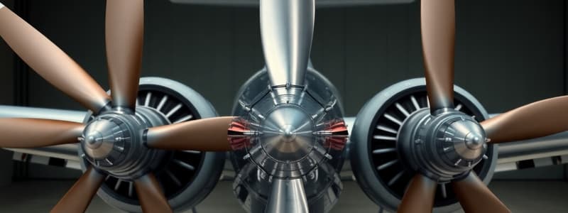
Propeller Synchronisation
- This minimizes vibration and noise caused by propellers vibrating at slightly different frequencies
- Beat frequency is the annoying phenomenon caused by two vibrating bodies vibrating at slightly different frequencies
- A synchronizing system sets all propellers to the same RPM to minimize excess beat frequency noise and vibration
- Aircraft vibration has always been a major problem because of the lightweight structure that cannot absorb it
- Slight variations in propeller speed in multi-engine aircraft cause harmful vibration and annoyance that has a low fundamental frequency almost equal to the difference between engine speeds
- Minimizing vibrations involves selecting one engine as the master engine
- When a pilot adjusts the master engine's RPM, the synchronizer system automatically adjusts the slave engine's RPM to match
- Once switched on, the system is automated but is not used during takeoff and landing.
General Operation
- Used in all flight phases except takeoff and landing
- Using the system during takeoff or landing could result in all engines trying to follow the master engine, causing complete power loss if the master engine fails and its RPM decreases by 100 RPM
- In normal operation, the synchronisation system compares the signals of the master and slave engines through a comparison unit
- The comparison unit causes the slave engines' governors to adjust their RPM to match the master engine RPM within 100 RPM
- With a master control system added, all engine RPM can be adjusted using the master control lever
- Moving the master control lever interrupts the synchronisation system, and the engines go out of synchronisation for a few seconds
- Once the lever is stationary, the system returns to synchronisation
Alternator Method
- Detects changes in the speed of a slave engine using engine-driven synchronizing alternators
- Each alternator's output voltage is proportional to its engine speed and sent to the corrector motor on the slave engine
- This modifies the slave engine's RPM if there is any output difference compared to the master engine
- The corrector motor has two stators mounted on a common rotor: one connected to the master engine alternator, and the other to the slave alternator
- The wiring from the alternators is such that the magnetic fields produced in the stators are in opposition
- Output from the common shaft goes is via a clutch assembly and reduction gear to the slave engine throttle controls
- The rotation of the shaft moves the control lever slightly and activates the input rods to the fuel and propeller control unit (governor) of the engines
- The PCU operation either increases or decreases the blade pitch, depending on the direction of correction, causing the slave engine's RPM to match the master engine's speed
- The stator windings in the correction motor are wired so the slave motor influences the rotor in the decrease RPM direction and the master stator influences it in the increase RPM direction
- The comparison unit's limited range of operation requires the slave engines to be within approximately 100 RPM of the master engine RPM for synchronization to occur
- The system's limited range is designed so that a master engine failure or overspeed only affects the slave engine to a certain extent
- A datum cam on the output shaft returns the corrector motor to the mid-point of the operating range when the system is switched off.
Magnetic Pickup Method
- The synchroniser system consists of two engines, where one is designated as the master engine
- When the pilot adjusts the master engine's RPM, the synchroniser system automatically adjusts the slave engine's RPM
- Each propeller governor contains a rotating magnet and a magnetic pickup
- As a governor rotates, it produces alternating current, and its frequency is proportional to the governor's speed
- The outputs from the two governors are compared in the synchroniser control box
- An output signal is sent to the DC stepper motor actuator, connected to the propeller governor bell crank on the fuel control of the slave engine
- If the slave engine's RPM is slower than the master engine's, the control box drives the actuator motor in a direction that moves the bell crank and connection arm on the slave motor fuel control, and the propeller governor increases its RPM
- The system is not used during takeoff and landing and is simple to operate
- During cruise flight, the condition levers of the engines are manually adjusted and brought close enough that the engines are within the synchronising range
- Then, the synchroniser is turned on, and any RPM difference is sensed
- The slave engine fuel control and propeller governor are adjusted to match the RPM of the master engine
- When making power changes in flight, adjust both condition levers together to keep the RPM within synchronising range
- If the engines get out of synchronisation beyond the system limits, the actuator drives to its limit of travel
- Turn the system off, manually synchronise the engines, and turn the system back on to fine-tune the synchronisation
Synchroscope
- Many multi-propeller engine aircraft have a synchroscope, a visual indicator that displays RPM differences between a master engine and slave engines
- A magnetic pickup sensor, located inside the propeller reduction gearbox, monitors the speed of each engine's propeller
- The synchroscope indicator displays a miniature propeller for each slave engine that rotates when an RPM difference exists, indicating whether the slave is faster or slower than the master
- Signals from the propeller control unit of the master engine and the slave engines are sent to a control unit, where they are compared
- When engaged, any RPM difference between the master and slave engines is detected in the control unit
- The control unit generates positive or negative current outputs sent to torque motors on the slave engine propeller control units
- A signal indicating the slave engine is running slower or faster causes the torque motor to adjust its propeller pitch to fine-tune or coarsen its speed
- This process continues until no difference exists between the slave and master engine speeds
- The torque motor rotation resets the speeder spring on the affected slave engine's propeller control unit, ensuring it is finally synchronized with the master engine
Synchrophasing
- Ensures adjacent propeller tips are separated by a particular angle to reduce noise levels
- Although synchronizing the propellers eliminates beat noise, it doesn't significantly reduce noise and vibration
- The interaction between blades of adjacent propellers, especially when the tips are opposite each other is a main cause of noise
- Controlling the angular difference between adjacent blades minimizes noise levels
- Synchrophasing allows the pilot to set the slave engines' blades to be a certain number of degrees behind the master engine's blades
- The pilot can adjust the synchrophase angle to suit different flight conditions while maintaining a minimum noise level
- A pulse generator is synchronized to the same blade of each propeller
- By comparing signals from the engines, a signal is sent to the slave governor, causing them to establish the phase angle chosen by the pilot
Operation of Synchrophasing
- A pulse generator is connected to the same blade of each propeller (blade #1), generating a signal that determines whether all #1 blades are in the same relative position at the same moment
- The pulse generator functions like a tachogenerator in the synchronization system
- The synchrophasor computer receives and compares signals from the pulse generators to the master engine signal, and sends a correcting signal to the governors
- The governors adjust the control of the slave engine(s) to establish the correct propeller phase angle.
FADEC Controlled Engines
- The engine control computer calculates propeller synchronization on these engines
- There is a master engine (usually engine #1) that sends signals to the other engine control computer(s) to adjust propeller speed and phase
- FADEC controlled engines operate in different modes based on flight configuration and power lever setting
- Propeller synchronization is typically automatic during propeller forward thrust and constant speed operations when all engines work normally
- The left-hand (LH) and right-hand (RH) propeller control systems automatically enter synchronization mode when they are in constant speed mode with less than 100 RPM difference between the speed of the two propellers and the speed the engine control computers have set
- In synchronization mode, the LH and RH engine control computers use pulse probes to identify the position of the blades on each propeller
- The RH engine control computer compares the master pulse signals (LH propeller) with its own
- If there is a difference in blade phase angle, the RH engine control computer sends adjusting signals to its own governor until the phase angle on both propellers becomes correct
- To maintain the pulse signals in the correct relationship with the master pulse signals, the RH engine control computer continuously adjusts its propeller governor
- The propeller control systems exit their synchronization mode when the RH engine control computer can no longer maintain the same speed and correct phase angle compared to the master engine
- The propeller control system also exits synchronization mode if there is an engine shutdown.
Studying That Suits You
Use AI to generate personalized quizzes and flashcards to suit your learning preferences.