Podcast
Questions and Answers
What type of diagram represents a flow scheme in a sequential block form?
What type of diagram represents a flow scheme in a sequential block form?
- Mechanical flow diagram
- Pipe and instrumentation diagram
- Process flow diagram
- Block flow diagram (correct)
Which of the following is true about a pipe and instrumentation diagram?
Which of the following is true about a pipe and instrumentation diagram?
- It shows detailed control loops.
- It includes operational hazards.
- It indicates general flow but lacks major equipment.
- It does not show minor details of the process. (correct)
In which part of the remote balloon symbol should the letters identifying the instrument be placed?
In which part of the remote balloon symbol should the letters identifying the instrument be placed?
- Bottom portion
- Middle portion
- Top portion (correct)
- Outside area
What is indicated by the first letter in an instrument identification tag, such as 'LIC 100'?
What is indicated by the first letter in an instrument identification tag, such as 'LIC 100'?
What does the abbreviation 'AAH' stand for in instrumentation?
What does the abbreviation 'AAH' stand for in instrumentation?
What key function does a legend on a P&ID serve?
What key function does a legend on a P&ID serve?
Which of the following is NOT a requirement for a P&ID according to the content?
Which of the following is NOT a requirement for a P&ID according to the content?
What does cross-hatching on a P&ID typically denote?
What does cross-hatching on a P&ID typically denote?
An isometric diagram can be described as which of the following?
An isometric diagram can be described as which of the following?
Which of the following statements about a mechanical flow diagram is true?
Which of the following statements about a mechanical flow diagram is true?
Study Notes
Block Flow Diagram
- Block flow diagram shows a sequential flow scheme
Process Flow Diagram
- Shows the general flow of the process
- Uses symbols to represent major equipment
- Does not include minor details like instrumentation control loops
Pipe and Instrumentation Diagram (P&ID)
- Shows the interconnection of process equipment and the instrumentation used to control the process
- Instrument identification (tag numbers) use letters and numbers
- The first letter indicates which process variable is being measured
- The second letter stands for indicator
- The third letter stands for control
- Example: LIC 100 - Level Indicator Control
- Symbol AAH stands for Analyzer Alarm High
Remote Balloon Symbol
- Letters identifying the instrument are placed at the top of the balloon
- Numbers are placed at the bottom of the balloon
P&ID Legend
- Shows the meaning of the symbols used in the diagram
Mechanical Flow Diagram
- Shows metallurgy, line sizes, and flange ratings
Isometric Diagram (ISO)
- 3-D drawing
P&ID Revision
- Cross hatching denotes a revision
P&ID Key Functions
- Unique identification number
- Shows connections between instruments
- Shows instrument locations
- Describes instrument functions
Studying That Suits You
Use AI to generate personalized quizzes and flashcards to suit your learning preferences.
Description
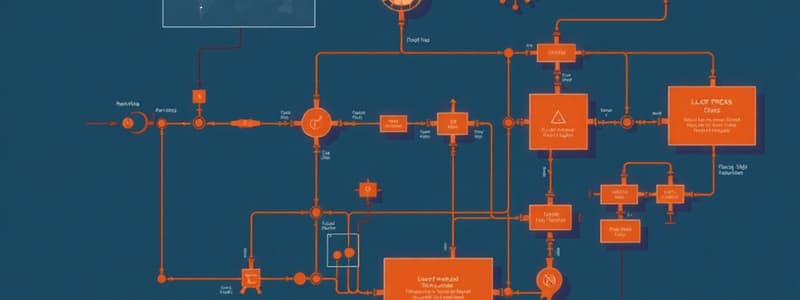
Explore the key concepts and symbols used in Block Flow Diagrams, Process Flow Diagrams, and Pipe and Instrumentation Diagrams (P&ID). This quiz will cover the sequential flow schemes, important equipment symbols, and the specific identification of instruments in the P&ID. Test your knowledge on these essential diagrams in process engineering.


