Podcast
Questions and Answers
When holding a bracket directly on a standard vise instead of machining a V-shape moving jaw, what is a primary disadvantage?
When holding a bracket directly on a standard vise instead of machining a V-shape moving jaw, what is a primary disadvantage?
- Hangover, causing vibrations and a rough surface finish. (correct)
- Reduced clamping force leading to part slippage.
- Inability to machine angled features on the bracket.
- Increased setup time due to complex fixturing.
A student forgets to re-establish the work offset G55 after facing in the first setup and before proceeding to the second operation that relies on G55. What is the most likely outcome?
A student forgets to re-establish the work offset G55 after facing in the first setup and before proceeding to the second operation that relies on G55. What is the most likely outcome?
- The second operation will run, but the part dimensions will be incorrect due to a shifted origin. (correct)
- The machine will automatically correct the offset based on the toolpath.
- The tool will break due to incorrect cutting parameters.
- The machine will display an error message and halt the operation.
In a 3rd setup, a 3D taster is used to contact a stopper to establish the X-axis Work Offset G56. The machine position at touch is -469.1453, and the work origin X-axis after setup is -428.1453. Why is the difference between these values consistently 41mm?
In a 3rd setup, a 3D taster is used to contact a stopper to establish the X-axis Work Offset G56. The machine position at touch is -469.1453, and the work origin X-axis after setup is -428.1453. Why is the difference between these values consistently 41mm?
- It is due to an inherent machine error that requires calibration.
- It represents the radius of the 3D taster.
- It is a preset safety margin to prevent collisions in the X-axis.
- The bar stopper and the machine position when it touches the stopper creates a fitting datum, and to find the center, the work origin X-axis after setting up is always in the middle. 8 + 33/2 = 41.0mm (correct)
When creating a counterbore of Ø20 x 2 in the 3rd setup, why is it recommended to use a Ø16 HSS endmill with a pocketing operation instead of a Ø20 endmill using a simple drilling cycle?
When creating a counterbore of Ø20 x 2 in the 3rd setup, why is it recommended to use a Ø16 HSS endmill with a pocketing operation instead of a Ø20 endmill using a simple drilling cycle?
In which scenario is tool wear compensation most critical during machining?
In which scenario is tool wear compensation most critical during machining?
In CNC milling, which of the following is the primary reason for using parallel bars?
In CNC milling, which of the following is the primary reason for using parallel bars?
A raw stock with a surface height of 40mm is clamped in a vise. The clamping depth required is 5mm, and a minimum clearance of 1mm is needed for safe cutting. If the raw stock surface is then face milled down 8.5mm, what range of parallel bar heights 'A' is most suitable for this setup?
A raw stock with a surface height of 40mm is clamped in a vise. The clamping depth required is 5mm, and a minimum clearance of 1mm is needed for safe cutting. If the raw stock surface is then face milled down 8.5mm, what range of parallel bar heights 'A' is most suitable for this setup?
When determining the overall thickness of a workpiece using a 3D measuring probe, what is the correct procedure?
When determining the overall thickness of a workpiece using a 3D measuring probe, what is the correct procedure?
After flipping the workpiece, establishing the G55 work offset is essential for the second side machining. What is the most accurate method to determine this offset?
After flipping the workpiece, establishing the G55 work offset is essential for the second side machining. What is the most accurate method to determine this offset?
A student forgets to re-establish the Work Offset G55 after facing a workpiece. What is the likely consequence of this error?
A student forgets to re-establish the Work Offset G55 after facing a workpiece. What is the likely consequence of this error?
In a CNC milling operation, what is the primary reason for performing tool wear compensation?
In a CNC milling operation, what is the primary reason for performing tool wear compensation?
Why might tool wear compensation be deemed unnecessary when machining a 75mm slot?
Why might tool wear compensation be deemed unnecessary when machining a 75mm slot?
When planning a milling operation, why is it crucial to consider the direction of the cutting force?
When planning a milling operation, why is it crucial to consider the direction of the cutting force?
When machining a bracket, which orientation (as shown in the 'bracket part orientations' diagram) is preferred and why?
When machining a bracket, which orientation (as shown in the 'bracket part orientations' diagram) is preferred and why?
Why is it generally necessary to pre-drill a hole before using an endmill to create a bore hole, and what is an alternative method?
Why is it generally necessary to pre-drill a hole before using an endmill to create a bore hole, and what is an alternative method?
Why is it generally recommended to machine a bore hole from one side instead of machining from both sides in separate setups?
Why is it generally recommended to machine a bore hole from one side instead of machining from both sides in separate setups?
During a second setup, if a measured dimension of 12.2mm is obtained instead of the required 12mm, what adjustment can be made to the machine's work coordinate system to correct this?
During a second setup, if a measured dimension of 12.2mm is obtained instead of the required 12mm, what adjustment can be made to the machine's work coordinate system to correct this?
In a CNC milling operation, given a depth of cut of 28mm and a feed rate of 2500 mm/min, what is the significance of monitoring the chip thickness, and what does a typical value like 0.24mm indicate?
In a CNC milling operation, given a depth of cut of 28mm and a feed rate of 2500 mm/min, what is the significance of monitoring the chip thickness, and what does a typical value like 0.24mm indicate?
When using a vise with a V-shaped moving jaw to secure a bracket for CNC milling, how is the Y-coordinate of the G55 work offset typically determined in the second setup?
When using a vise with a V-shaped moving jaw to secure a bracket for CNC milling, how is the Y-coordinate of the G55 work offset typically determined in the second setup?
A student forgets to re-establish the work offset G55 after facing the first side of a workpiece. What is the most likely consequence when machining the second side?
A student forgets to re-establish the work offset G55 after facing the first side of a workpiece. What is the most likely consequence when machining the second side?
In what scenarios is tool wear compensation most critical, and why might it be unnecessary in certain machining steps?
In what scenarios is tool wear compensation most critical, and why might it be unnecessary in certain machining steps?
Flashcards
Bracket on standard vise
Bracket on standard vise
Holding the bracket directly on the standard vise simplifies setup by eliminating v-shaped machining.
Vibrations causing rough finish
Vibrations causing rough finish
Holding the bracket directly can introduce vibrations, leading to a poor surface finish.
Work Offset G55 for Z direction
Work Offset G55 for Z direction
The datum face is essential for establishing the Z-axis work offset in CNC setting.
Difference between positions on X-axis
Difference between positions on X-axis
Signup and view all the flashcards
Using Ø20 end mill for counterbore
Using Ø20 end mill for counterbore
Signup and view all the flashcards
Achieving 12mm measurement
Achieving 12mm measurement
Signup and view all the flashcards
Orientation selection for machining
Orientation selection for machining
Signup and view all the flashcards
Dynamic milling time for bracket
Dynamic milling time for bracket
Signup and view all the flashcards
Depth of cut and feed rate
Depth of cut and feed rate
Signup and view all the flashcards
Pre-drilling necessity
Pre-drilling necessity
Signup and view all the flashcards
Helical ramping alternative
Helical ramping alternative
Signup and view all the flashcards
First setup bore hole importance
First setup bore hole importance
Signup and view all the flashcards
Determining G55 Y-Coord Offset
Determining G55 Y-Coord Offset
Signup and view all the flashcards
Parallel Bars Purpose
Parallel Bars Purpose
Signup and view all the flashcards
Height of Parallel Bars
Height of Parallel Bars
Signup and view all the flashcards
Min Clamping Depth
Min Clamping Depth
Signup and view all the flashcards
Min Clearance Requirement
Min Clearance Requirement
Signup and view all the flashcards
Caster Base Thickness Measurement
Caster Base Thickness Measurement
Signup and view all the flashcards
Establishing Work Offset G55
Establishing Work Offset G55
Signup and view all the flashcards
Consequences of Missing Offset G55
Consequences of Missing Offset G55
Signup and view all the flashcards
Tool Wear Compensation Necessity
Tool Wear Compensation Necessity
Signup and view all the flashcards
Study Notes
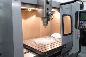
CNC Milling Lab Practical Sessions
- Session 2: Focuses on practical exercises using parallel bars in CNC milling.
- Parallel bars lift the workpiece preventing collisions with the table or vise.
- They ensure the workpiece is parallel to the working surface.
- Parallel bar height was 35mm.
- Measurements of 'B' (vise clamping depth) and 'A' (parallel bar height range) were taken to establish safe cutting parameters. Calculations were needed to determine the safe working range.
- Session 3: Examines establishing overall thickness and work zero for machining a caster base.
- Thickness tolerance is ±0.1mm.
- Obtaining the overall thickness involves using a probe to measure the piece, and entering the measured value (+ or - tolerance) into the machine tool.
- G55 work offset determination is crucial for machining the second side of the workpiece after the stock is flipped. Steps detailing the process of calculating x, y coordinates are required.
- Session 4: Focuses on machining a bracket.
- Determines the best bracket orientation for machining (Diagram A was chosen).
- Justification for orientation choice: Lower sliding chance and better control.
- Machining time for roughing out the bracket is given (1 minute 5 seconds).
- Observation on the machining technique (e.g., the measurement of depth, feed rate, etc.) is noted.
- Tolerances, measurements, and the implications of incorrect tooling settings were examined.
- Techniques for creating a Ø22.03mm bore hole and considerations for machining the bore hole from different sides.
- Session 5: Includes determining machine coordinates and machining considerations for milling operations.
- Method for determining the G55 Y-coordinate work offset for the second setup. This is associated with work holding.
- Evaluation of alternative work-holding methods for the bracket. Advantages and disadvantages are listed for each method.
- Datum face for establishing the work-offset G55 for the Z-direction is identified as part of a diagram.
- Explanation of why the difference in machine positions (a) and (b) (from the diagram) above is always 41 mm.
- Reasons why a Ø20 end mill shouldn't be used to achieve the counterbore; this is linked to the size of the tool.
Studying That Suits You
Use AI to generate personalized quizzes and flashcards to suit your learning preferences.