Podcast
Questions and Answers
What is the purpose of this procedure?
What is the purpose of this procedure?
To define the procedure for safe and effective welding repairs on cracks found in mobile equipment chassis and structural components, ensuring adherence to AWS D1.1/D14.3 standards for structural integrity and safety.
What are two types of trucks this procedure applies to?
What are two types of trucks this procedure applies to?
EH3500 and EH4000
The responsibility for safety lies solely with the welding technicians.
The responsibility for safety lies solely with the welding technicians.
False (B)
What type of welding process is recommended in this procedure?
What type of welding process is recommended in this procedure?
What is the minimum acceptable length for a tack weld?
What is the minimum acceptable length for a tack weld?
What type of welding is commonly used for box section structures?
What type of welding is commonly used for box section structures?
What is the minimum acceptable thickness for a backing plate?
What is the minimum acceptable thickness for a backing plate?
What is the maximum permissible interpass temperature?
What is the maximum permissible interpass temperature?
Flashcards
Chassis Welding Procedure
Chassis Welding Procedure
A procedure for safely and effectively repairing cracks in mobile equipment chassis and structural components.
AWS D1.1/D14.3 Standards
AWS D1.1/D14.3 Standards
Standards for structural integrity and safety in welding repairs, used for mobile equipment.
Revision Table
Revision Table
A table that tracks changes made to a document, showing dates, changes, and preparers.
Welding Procedure Specification (WPS)
Welding Procedure Specification (WPS)
Signup and view all the flashcards
Parts Cleaning and Inspection
Parts Cleaning and Inspection
Signup and view all the flashcards
Excavation
Excavation
Signup and view all the flashcards
Backing Strips
Backing Strips
Signup and view all the flashcards
Welding Process
Welding Process
Signup and view all the flashcards
Tack Welding
Tack Welding
Signup and view all the flashcards
Site Safety Precautions
Site Safety Precautions
Signup and view all the flashcards
Personal Protective Equipment (PPE)
Personal Protective Equipment (PPE)
Signup and view all the flashcards
Scope
Scope
Signup and view all the flashcards
Responsibility
Responsibility
Signup and view all the flashcards
Qualifications
Qualifications
Signup and view all the flashcards
Purpose
Purpose
Signup and view all the flashcards
Mobile Equipment
Mobile Equipment
Signup and view all the flashcards
Repair Procedure
Repair Procedure
Signup and view all the flashcards
Structural Components
Structural Components
Signup and view all the flashcards
Kansanshi Standard
Kansanshi Standard
Signup and view all the flashcards
Eff. Date
Eff. Date
Signup and view all the flashcards
Rev: 1
Rev: 1
Signup and view all the flashcards
Safety Requirements
Safety Requirements
Signup and view all the flashcards
Welding Standards
Welding Standards
Signup and view all the flashcards
Study Notes
Chassis Welding Procedure
- Document Title: Chassis Welding Procedure – EH3500, EH4000
- Purpose: Define procedure for safe and effective welding repairs on cracks in mobile equipment chassis, adhering to AWS D1.1/D14.3 standards for structural integrity and safety.
- Change Description: Change to Kansanshi Standard
Revision Table
- 0: New Procedure (Prepared by Miguel Rodriguez)
- 1: Scheduled Review
- 2: Change to procedure
Approval List
- Alan Romero (Reliability Superintendent), 22-11-2024
- Charl Vermaak (Maintenance Superintendent), 22/11/2024
- Mwausa Kombe (Welding Superintendent), 22-11-2024
- Gregory Mwanza (Mobile Maintenance Manager), 22-11-2024
Contents
- Revision table: Page 2
- Purpose: Page 4
- Scope: Page 4
- Safety Requirements: Page 4
- Site Safety Precautions: Safety is employee responsibility; study repair drawings; select tools/equipment; authorization from site management
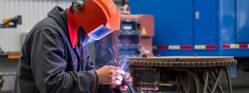
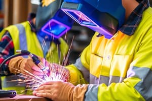
- Personal Protective Equipment (PPE): Ensure all personnel wear suitable PPE, including helmets, gloves, glasses, masks, ear protection, face shields, fire-resistant clothing
- Welding Standards and Repair Procedures: Page 5
- Responsibility and Qualifications: Page 5
- Qualified Welding Technician: D1.1, 3G/4G, groove weld qualification, unlimited (plate thickness). Welding repair supervisor: five years experience
- Condition Monitoring/NDT Inspector: SNT-TC-1A – Level II
- Welding Procedure Specification (WPS): Page 5
- Welding process: FCAW
- Electrode: AWS 5.29, E81T1N1-H4 and E111T1- H4 gas mix 75%-25% Argon/Co2
- Preheat: When ambient temperature is below 10°C (50 °F) and/or humidity, preheat base metal to 30-50°C (86-122°F).
- Welding Process: Page 12
- Use Flux Core Arc Welding (FCAW)
Safety Precautions
- Safety is employee responsibility
- Tools/equipment must be appropriate to the task
- Only authorized personnel may perform welding
- Risk assessments must be completed before commencing work
- Fireproof barriers and flammable materials are to be cleared
Welding Specifications
- Preheat area for 3" or 75 mm away from the crack. Maintain this temperature throughout the repair.
- Infrared devices not recommended for preheating due to accuracy issues on smooth/shiny metals
- Measure temperature at 50-100 mm from the joint
- Use Temperature Sticks for root welding
- Preheat Temperature Log Sheet (sample layout) is provided
- Maximum temperature between welding passes must be between preheat temperature and 400°C (752°F).
- Insulate weld after completion for controlled cooling
- Groove angle between 45° - 60° for grooves (“V” or “U”)
- Backing plates (if needed), should be continuous weld
- Dimensions of weld to specifications.
Technical Requirements
- Parts cleaning of repair areas (mechanical/chemical)
Excavation and Weld Preparation
- Repair existing defects using grinding and arc-air gouging
- Remove slag, oxides, carburized zones from the excavation
- Confirm the thickness of the plate before gouging
- Maintain smooth transitions during excavation
- If crack propagation is suspected, use holes to prevent further damage
- Weld metal/base metal removal can not damage the adjacent material
Backing Strips
- Precautions for use with box sections: Prep access holes; Perform repair work through access holes; Use backing plates
- Material of backing plate to suit base metal; Install with no gaps to avoid stress concentration.
- Install backing plates to cover access holes by tack welding
- Remove tack welds before performing final welding
- Avoid using backing plates more than 40 to 50 mm from end edge
Welding Process
- Use Flux Core Arc Welding (FCAW)
- Tack welding parameters same as subsequent weld
- Minimum tack weld length = 50 mm
- Remove any defective tack welds
Welding of Run-Off Tabs
- Adapt size of tabs to cover weld bevels
- Shortest distance from start/stop of welding layers to plate = 40 mm
Welding Positions
- Positions: flat, horizontal, vertical (up progression), overhead
- Groove: 1G, 2G, 3G, 4G; Fillet: 1F, 2F, 3F, 4F
Welding Technique
- Weld the root pass along the crack
- Remove slag from the root pass. Visually check for cracks
- Any crack found is to be gouged out, edges are to be smoothed, and re-welded
- Continue bead for a full pass, before starting second pass
Interpass Temperature
- Measure and record interpass temperature every hour
- Maximum allowed temperature is 400°C
Order of Weld Finish Passes
- Pass 1: Make weld at parent material edge
- Pass 2: Weld with 50% overlap on Pass 1
- Pass 3: Weld with 50% overlap on Pass 2
- Final weld: Middle of weld area away (from) parent metal
Defects Avoidance/Corrections
- Avoid crack propagation
- Check for cracks in the root pass and adjacent weld layers
Grinding Procedures
- Grind all welds smooth.
- Grind to a smooth weld transition to the base
- Grind to a radius of 2 inches
- Grind feed marks/polish
- Ensure reinforcement is flat
- A standard 4" or 4.5" grinding wheel
Final Weld Inspection
- Inspect welds within 48 hrs of completion, while cooled
- Visual Inspection, MT, or UT inspection
- No cracks or undercuts
Paint
- Clean welds and paint with primer and top coat
Documentation
- Record all inspection results (NDT findings, weld parameters, etc.) and retain them in the equipment’s maintenance history
Repair Standards and References
- Welding standards: AWS D1.1, Structural Welding Code – Steel, AWS 14.3, and AWS A5.29
- Repair welding manuals: Part No. KO-111-01
- Non-Destructive Testing (NDT) per requirements of AWS D1.1 and SNT-TC-1A
Studying That Suits You
Use AI to generate personalized quizzes and flashcards to suit your learning preferences.


