Phasor diagram for load condition (under excitation) and derivation for back EMF.
Understand the Problem
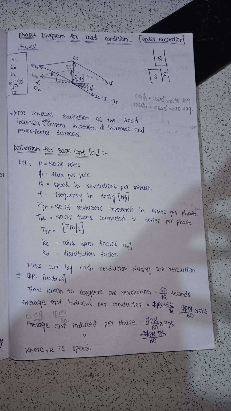
The question involves discussing a phasor diagram for a load condition under excitation in an electrical context, focusing on the relationship between load, current, excitation, and derived formulas for back EMF in electric machines. It seems to require understanding electrical engineering principles.
Answer
Phasor diagram shows E_b < V for under-excitation. Back EMF formula uses speed, flux, poles.
The image describes the phasor diagram and defines conditions under which the back EMF (E_b) is less than terminal voltage (V) for a synchronous motor in under-excitation mode. It also provides a formula for calculating the back EMF based on the speed, number of poles, and other factors.
Answer for screen readers
The image describes the phasor diagram and defines conditions under which the back EMF (E_b) is less than terminal voltage (V) for a synchronous motor in under-excitation mode. It also provides a formula for calculating the back EMF based on the speed, number of poles, and other factors.
More Information
In under-excited conditions, the synchronous motor's back EMF is smaller than the terminal voltage, which can influence power factor and stability.
Tips
Common mistakes include incorrect angle interpretation in phasor diagram and misuse of EMF formula with wrong number of poles or flux values.
Sources
- Expression For Back E.M.F Or Induced E.M.F. Per Phase In S.M. - electricallive.com
- Phasor Diagram for Synchronous Motor - Electrical4U - electrical4u.com
AI-generated content may contain errors. Please verify critical information