Draw the moment diagram for the beam.
Understand the Problem
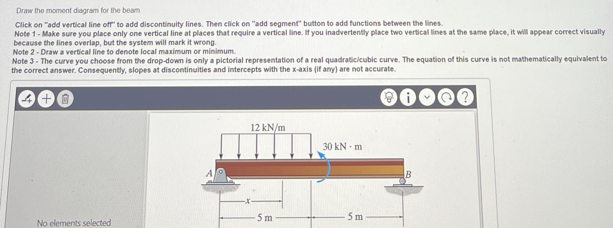
The question asks to draw the moment diagram for a beam, given a diagram with a distributed load of 12 kN/m over 5 meters and a point moment of 30 kN*m at the center, with the beam supported at points A and B, 5 meters apart.
Answer
The moment diagram comprises a quadratic curve from 0 to -30 $kN \cdot m$ followed by a jump discontinuity of 30 $kN \cdot m$ to 0 $kN \cdot m$ and then remains at zero.
Answer for screen readers
The moment diagram starts at 0 at support A, follows a quadratic curve down to -30 $kN \cdot m$ just before the applied moment at $x = 5$ m. At $x = 5$ m, there is a jump to 0 $kN \cdot m$ due to the applied moment. From this point it stays at 0 $kN \cdot m$ until the last support at $x=10$.
Steps to Solve
- Calculate the reactions at the supports
Since the structure is symmetric and has a point moment at the center, the reactions at supports A and B will be equal. The total downward force due to the distributed load is $12 \text{ kN/m} \times 5 \text{ m} = 60 \text{ kN}$. Therefore, each support will carry half of that load, plus we need to consider the effect of the moment. Taking the sum of the moments about point A:
$$ \sum M_A = 0 = -30 \text{ kN}\cdot\text{m} - (60 \text{ kN}) (2.5 \text{ m}) + R_B (5 \text{ m}) $$
Solving for $R_B$:
$$ R_B = \frac{30 + 60 \times 2.5}{5} = \frac{30 + 150}{5} = \frac{180}{5} = 36 \text{ kN} $$
Since the reactions must balance the applied load plus the effect of the moment:
$$ R_A + R_B = 60 \text{ kN} $$
$$ R_A = 60 - R_B = 60 - 36 = 24 \text{ kN} $$
- Determine the moment equation for the first section (0 m $\leq$ x $\leq$ 5 m)
Taking a cut at a distance $x$ from support A:
$M(x) = R_A \cdot x - \frac{1}{2} (12 \text{ kN/m}) x^2 = 24x - 6x^2 $
- Calculate the moment at x=0 m and x=5 m
$M(0) = 24(0) - 6(0)^2 = 0 \text{ kN}\cdot\text{m}$
$M(5) = 24(5) - 6(5)^2 = 120 - 150 = -30 \text{ kN}\cdot\text{m}$
- Consider the applied moment
At $x=5$ m, there is a point moment of $30 \text{ kN}\cdot\text{m}$ is applied. Since it is a negative moment (clockwise), this will cancel part of the beam's internal moment.
- Determine the moment equation for the second section (5 m $\leq$ x $\leq$ 10 m)
Taking a cut at a distance $x$ from support A, and including the effect of the point moment:
Starting from the section at position $x$:
$M(x) = R_A \cdot x - (\text{distributed load}) \cdot (x-2.5) \cdot \frac{x-2.5}{2} - 30 $ for one portion. So
$$ M(x) = 24x - 6x^2$$ Then since we have a point moment at 5m, we will have just that value there i.e. $-30 \text{ kN}\cdot\text{m}$ at $x=5$.
Then, after 5 m to the bearing support B, or $10$ m: $M(10) = 0$
Alternatively, one can consider the moment as a function to be determined by sections of the beam as follows:
For $0 \leq x \leq 5$: $M(x) = 24x - 6x^2$
At $x=5$, we have $M(5) = 24(5) - 6(5^2) = 120 - 150 = -30$. Then, the $30 \text{ kN}\cdot\text{m}$ is applied at 5m and therefore from here we have: $M(x') = -30$. Then since $x' = x-5, \text{ }x = x' + 5$. $M(x)= 36 * (10-x) = 360 - 36x $ Let $x'= 0 , x = 5$. $M(5) = 360 - 36(5) = 360-180 = 180 $ If $M(x)= 6*(10-x)(10-x)$ Let $x'= 0 , x = 5$. $M(5) = 6(5)*(5) = 150 $
- Final Moment diagram
The moment diagram will start from 0 at support A, follow a quadratic curve down to -30 kN*m just before the applied moment at x=5 m. At x=5 m, there is a jump in the diagram due to the applied moment to 0. Then the diagram follows a linear path to 0 at the support B.
The moment diagram starts at 0 at support A, follows a quadratic curve down to -30 $kN \cdot m$ just before the applied moment at $x = 5$ m. At $x = 5$ m, there is a jump to 0 $kN \cdot m$ due to the applied moment. From this point it stays at 0 $kN \cdot m$ until the last support at $x=10$.
More Information
The moment diagram visually represents the internal bending moment along the length of the beam. It's essential for structural analysis and design to determine the maximum bending moment, which is crucial for selecting appropriate beam sizes and materials.
Tips
A common mistake might be not accounting for the point moment correctly in the moment diagram, especially the jump discontinuity it causes. Another mistake is to make error in determining the reaction forces - remember the symmetry in forces is affected by the point moment and load distribution.
AI-generated content may contain errors. Please verify critical information