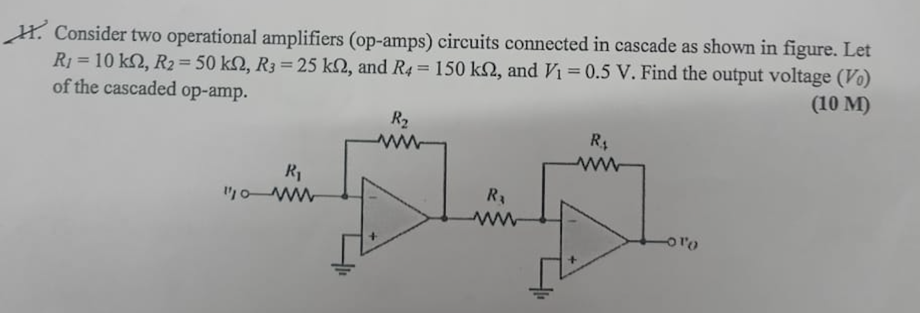
Consider two operational amplifiers (op-amps) circuits connected in cascade as shown in figure. Let R1 = 10 kΩ, R2 = 50 kΩ, R3 = 25 kΩ, and R4 = 150 kΩ, and V1 = 0.5 V. Find the ou... Consider two operational amplifiers (op-amps) circuits connected in cascade as shown in figure. Let R1 = 10 kΩ, R2 = 50 kΩ, R3 = 25 kΩ, and R4 = 150 kΩ, and V1 = 0.5 V. Find the output voltage (V0) of the cascaded op-amp.

Understand the Problem
The question is asking to analyze a circuit of two cascaded operational amplifiers (op-amps) to find the output voltage given specific resistor values and an input voltage. This involves applying the principles of operational amplifier circuits, including the effects of feedback and the relationship between input and output in each stage of amplification.
Answer
The output voltage \( V_0 \) is \( 15\,V \).
Answer for screen readers
The output voltage ( V_0 ) of the cascaded op-amps is ( 15,V ).
Steps to Solve
-
Calculate the output voltage from the first op-amp, ( V_{o1} )
For an inverting op-amp configuration, the voltage gain ( A_1 ) can be calculated using the formula: $$ A_1 = -\frac{R_2}{R_1} $$ Substituting the given values: $$ A_1 = -\frac{50,k\Omega}{10,k\Omega} = -5 $$
The output voltage ( V_{o1} ) from the first op-amp can be calculated with the input voltage ( V_1 ): $$ V_{o1} = A_1 \cdot V_1 = -5 \times 0.5,V = -2.5,V $$
-
Calculate the output voltage from the second op-amp, ( V_{o} )
Again, for the second op-amp, using the resistors ( R_3 ) and ( R_4 ): $$ A_2 = -\frac{R_4}{R_3} $$ Substituting the values: $$ A_2 = -\frac{150,k\Omega}{25,k\Omega} = -6 $$
The output voltage ( V_o ) from the second op-amp is: $$ V_o = A_2 \cdot V_{o1} = -6 \times (-2.5,V) = 15,V $$
The output voltage ( V_0 ) of the cascaded op-amps is ( 15,V ).
More Information
The feedback configuration of operational amplifiers allows significant amplification of the input signal. The gain can be easily calculated using resistor values, showcasing the linear behavior of these circuits under ideal conditions.
Tips
- Forgetting to consider the negative sign in the gain calculation. This indicates the phase inversion of the output.
- Not properly identifying the feedback configuration can lead to incorrect formulas being applied.
AI-generated content may contain errors. Please verify critical information