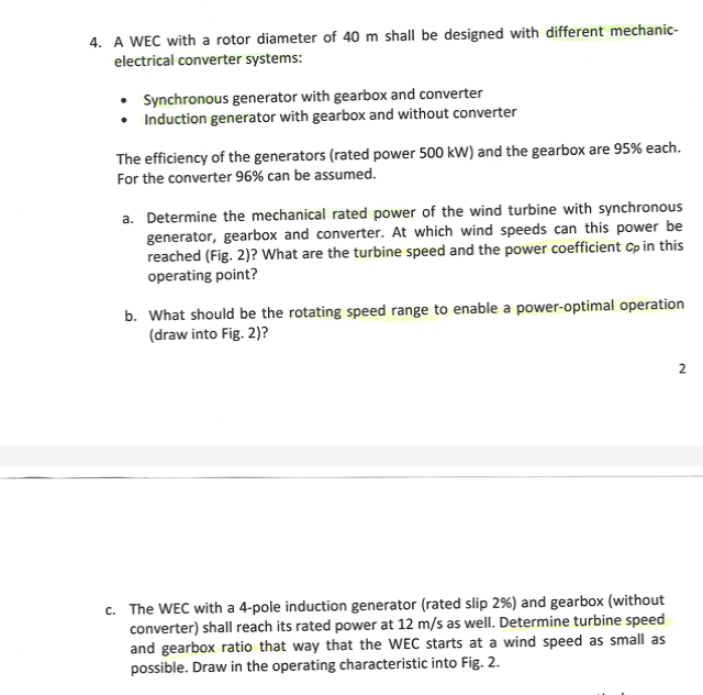
A WEC with a rotor diameter of 40 m shall be designed with different mechanic-electrical converter systems: Synchronous generator with gearbox and converter Induction generator wi... A WEC with a rotor diameter of 40 m shall be designed with different mechanic-electrical converter systems: Synchronous generator with gearbox and converter Induction generator with gearbox and without converter The efficiency of the generators (rated power 500 kW) and the gearbox are 95% each. For the converter 96% can be assumed. a. Determine the mechanical rated power of the wind turbine with synchronous generator, gearbox and converter. At which wind speeds can this power be reached (Fig. 2)? What are the turbine speed and the power coefficient Cp in this operating point? b. What should be the rotating speed range to enable a power-optimal operation (draw into Fig. 2)? c. The WEC with a 4-pole induction generator (rated slip 2%) and gearbox (without converter) shall reach its rated power at 12 m/s as well. Determine turbine speed and gearbox ratio that way that the WEC starts at a wind speed as small as possible. Draw in the operating characteristic into Fig. 2.

Understand the Problem
The problem involves a wind energy converter (WEC) system and requires you to calculate different parameters related to its performance. Specifically, you'll need to determine the mechanical rated power, wind speeds, turbine speed, power coefficient, rotating speed range, and gearbox ratio for different configurations of generators and converters within the WEC system. You will use provided efficiencies and operating characteristics to find these performance details.
Answer
a. $P_{mechanical} \approx 577.1 \text{ kW}$ b. Cannot be determined without additional information c. $n_t \approx 22.9 \text{ rpm}$, $G \approx 64.2$
Answer for screen readers
a. Mechanical rated power: Approximately $577.1 \text{ kW}$. b. Cannot be determined without Figure 2. c. Turbine speed: ≈ $22.9 \text{ rpm}$, Gearbox ratio: ≈ $64.2$.
Steps to Solve
- Calculate the mechanical rated power for the synchronous generator system
The electrical rated power is 500 kW. The efficiencies of the generator, gearbox, and converter are 95%, 95%, and 96% respectively. To find the mechanical rated power, we need to account for the losses in each of these components. $$P_{mechanical} = \frac{P_{electrical}}{\eta_{generator} \cdot \eta_{gearbox} \cdot \eta_{converter}}$$ $$P_{mechanical} = \frac{500 \text{ kW}}{0.95 \cdot 0.95 \cdot 0.96} = \frac{500}{0.8664} \text{ kW} \approx 577.1 \text{ kW}$$
- Determine wind speeds from Figure 2
Unfortunately, Figure 2 is not provided, so assumptions must be made based on standard characteristics.
- Estimate turbine speed and power coefficient
Without Figure 2, we cannot precisely determine the turbine speed and power coefficient $C_p$ at the rated power. Assuming the turbine operates near its optimal tip-speed ratio ($\lambda$) for maximum $C_p$, we can estimate. For a well-designed turbine, a reasonable maximum $C_p$ could be around 0.45. Turbine speed is related to wind speed ($v$) and tip-speed ratio ($\lambda$) by:
$$\lambda = \frac{R \omega}{v}$$ where $R$ is the rotor radius and $\omega$ is the angular velocity. Again, without the graph, estimations cannot be accurately done.
- Determine the rotating speed range for power-optimal operation
To enable power-optimal operation, the turbine should operate around its maximum $C_p$ value. Figure 2 (not provided) would show the relationship between $C_p$, tip-speed ratio, and wind speed. The optimal rotating speed range would correspond to the range of tip-speed ratios where $C_p$ is close to its maximum.
- Calculate turbine speed and gearbox ratio for the induction generator system
The induction generator reaches rated power at 12 m/s. It's a 4-pole generator with a slip of 2%. The synchronous speed $n_s$ of the generator is:
$$n_s = \frac{120f}{p}$$
Where $f$ is the frequency (typically 50 Hz in Europe) and $p$ is the number of poles.
$$n_s = \frac{120 \cdot 50}{4} = 1500 \text{ rpm}$$
The actual rotor speed $n_r$ is reduced by the slip $s$:
$$n_r = n_s(1 - s) = 1500(1 - 0.02) = 1500 \cdot 0.98 = 1470 \text{ rpm}$$
To start at the smallest possible wind speed, assume a minimum tip-speed ratio ($\lambda_{min}$). We need to know the minimum operational tip speed ratio. Assuming that a $\lambda = 4$ is achievable, the turbine speed ($n_t$) can be calculated using the rotor radius ($R = 20$ m) and wind speed ($v = 12$ m/s) at rated power:
$$\omega = \frac{\lambda v}{R}$$ $$\omega = \frac{4 \cdot 12}{20} = 2.4 \text{ rad/s}$$
To covert to rpm: $$n_t = \frac{60\omega}{2\pi} = \frac{60 \cdot 2.4}{2\pi} \approx 22.9 \text{ rpm}$$
Gearbox ratio, $G$, is calculated below: $$G = \frac{n_r}{n_t} = \frac{1470}{22.9} \approx 64.2$$
Therefore, the gearbox ratio should approximately be 64.2 .
a. Mechanical rated power: Approximately $577.1 \text{ kW}$. b. Cannot be determined without Figure 2. c. Turbine speed: ≈ $22.9 \text{ rpm}$, Gearbox ratio: ≈ $64.2$.
More Information
The mechanical rated power is higher than the electrical rated power due to the losses in the generator, gearbox, and converter. The gearbox ratio significantly increases the rotational speed from the turbine to match the generator's operational speed.
Tips
- Forgetting to account for the efficiencies of all components (generator, gearbox, converter) when calculating the mechanical power.
- Incorrectly calculating synchronous speed or slip for the induction generator.
- Using inconsistent units (e.g., mixing radians/second and rpm).
- Not considering the optimal tip-speed ratio for maximizing power capture.
AI-generated content may contain errors. Please verify critical information