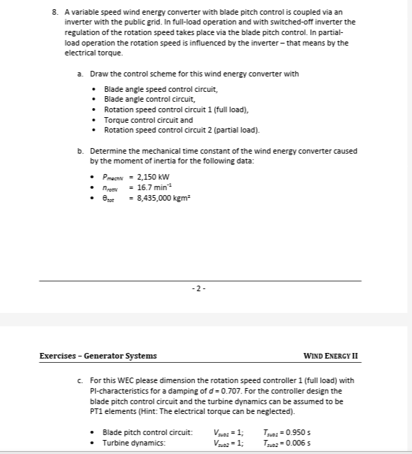
A variable speed wind energy converter with blade pitch control is coupled via an inverter with the public grid. In full-load operation and with switched-off inverter the regulatio... A variable speed wind energy converter with blade pitch control is coupled via an inverter with the public grid. In full-load operation and with switched-off inverter the regulation of the rotation speed takes place via the blade pitch control. In partial-load operation the rotation speed is influenced by the inverter - that means by the electrical torque. a. Draw the control scheme for this wind energy converter with * Blade angle speed control circuit, * Blade angle control circuit, * Rotation speed control circuit 1 (full load), * Torque control circuit and * Rotation speed control circuit 2 (partial load). b. Determine the mechanical time constant of the wind energy converter caused by the moment of inertia for the following data: $P_{mechN}$ = 2,150 kW $n_{rotN}$ = 16.7 min$^{-1}$ $\Theta_{tot}$ = 8,435,000 kgm$^2$ c. For this WEC, please dimension the rotation speed controller 1 (full load) with PI-characteristics for a damping of d = 0.707. For the controller design the blade pitch control circuit and the turbine dynamics can be assumed to be PT1 elements (Hint: The electrical torque can be neglected). * Blade pitch control circuit: $V_{sub1}$ = 1; $T_{sub1}$ = 0.950 s * Turbine dynamics: $V_{sub2}$ = 1; $T_{sub2}$ = 0.006 s
Understand the Problem
The question presents a problem related to a variable speed wind energy converter with blade pitch control. It asks to draw a control scheme, determine the mechanical time constant, and dimension the rotation speed controller with PI-characteristics. The problem involves concepts from control systems, mechanical engineering, and wind energy.
Answer
a. Control Scheme: Described in the steps above. b. $T_m \approx 11.97 \, \text{s}$ c. $K_p \approx 83.33$, $T_i = 0.950 \, \text{s}$
Answer for screen readers
a. Control Scheme: See explanation in "steps_to_solve" - a detailed diagram is difficult to create in this format.
b. The mechanical time constant is approximately $11.97 , \text{s}$.
c. The PI controller parameters are $K_p \approx 83.33$ and $T_i = 0.950 , \text{s}$.
Steps to Solve
-
Draw the Control Scheme: A detailed control scheme diagram is challenging to create directly in this text-based format. However, the essential structure can still be described. The control scheme incorporates several nested loops.
-
Blade Angle Speed Control Circuit (Outermost Loop): This loop compares the desired rotor speed with the actual rotor speed. The error signal is fed into a controller (typically a PI controller) which generates a blade pitch angle command.
-
Blade Angle Control Circuit (Inner Loop): This loop regulates the actual blade pitch angle. It compares the commanded blade pitch angle with the actual blade pitch angle, and a controller adjusts the blade pitch actuator accordingly.
-
Rotation Speed Control Circuit 1 (Full Load): This is active during full-load operation, where the inverter is switched off, and blade pitch control is primarily used for speed regulation. It is essentially the same as the blade angle speed control loop described above.
-
Torque Control Circuit: This loop controls the electrical torque produced by the generator through the inverter (during partial load). A torque reference signal is compared with the actual torque, and the inverter is controlled to minimize the error.
-
Rotation Speed Control Circuit 2 (Partial Load): This loop is active during partial-load operation. It uses the electrical torque controlled by the inverter to regulate the rotor speed. It compares the desired rotor speed with the actual rotor speed. The error signal is fed into a controller which generates a torque command for the torque control circuit.
-
Calculate the Mechanical Time Constant: First, convert the rotational speed from $min^{-1}$ to $s^{-1}$ (Hertz): $$n_{rotN} = 16.7 , \text{min}^{-1} = \frac{16.7}{60} , \text{s}^{-1} \approx 0.2783 , \text{Hz}$$ Next, calculate the angular velocity $\omega$ in rad/s: $$ \omega = 2 \pi n_{rotN} = 2 \pi (0.2783) \approx 1.748 , \text{rad/s} $$ Now that we have the angular velocity, we can find the rated mechanical torque $T_{mechN}$: $$ P_{mechN} = T_{mechN} \omega $$ Given that $P_{mechN} = 2150 , \text{kW} = 2150000 , \text{W}$, we have: $$ T_{mechN} = \frac{P_{mechN}}{\omega} = \frac{2150000}{1.748} \approx 1230000 , \text{Nm} $$ The mechanical time constant $T_m$ is defined as: $$ T_m = \frac{\Theta_{tot} \omega}{T_{mechN}} $$ Substituting the given values: $$ T_m = \frac{8435000 \cdot 1.748}{1230000} \approx 11.97 , \text{s} $$
-
Dimension the Rotation Speed Controller 1 (Full Load): Given that the blade pitch control circuit and turbine dynamics are PT1 elements, the open-loop transfer function is: $$ G_{open}(s) = \frac{V_{sub1}}{1 + sT_{sub1}} \cdot \frac{V_{sub2}}{1 + sT_{sub2}} \cdot G_c(s) $$ where $G_c(s)$ is the PI controller. The PI controller transfer function is: $$ G_c(s) = K_p + \frac{K_i}{s} = K_p \left( 1 + \frac{1}{sT_i} \right) $$ Where $K_p$ is the proportional gain and $T_i$ is the integral time constant. Substituting the given values $V_{sub1} = 1$, $V_{sub2} = 1$, $T_{sub1} = 0.950 , \text{s}$, $T_{sub2} = 0.006 , \text{s}$: $$ G_{open}(s) = \frac{K_p(1 + \frac{1}{sT_i})}{(1 + 0.95s)(1 + 0.006s)} $$ To achieve a damping of $d = 0.707$, we can use the pole-zero cancellation method. Set the integral time constant $T_i$ to be equal to the dominant time constant: $$ T_i = T_{sub1} = 0.950 , \text{s} $$ Then, the open-loop transfer function becomes: $$ G_{open}(s) = \frac{K_p}{s(1 + 0.006s)} $$ The closed-loop transfer function is: $$ G_{closed}(s) = \frac{G_{open}(s)}{1 + G_{open}(s)} = \frac{K_p}{0.006s^2 + s + K_p} $$ Comparing this to the standard second-order transfer function: $$ G(s) = \frac{\omega_n^2}{s^2 + 2d\omega_n s + \omega_n^2} $$ We get: $$ \omega_n^2 = \frac{K_p}{0.006} \implies \omega_n = \sqrt{\frac{K_p}{0.006}} $$ $$ 2d\omega_n = \frac{1}{0.006} \implies \omega_n = \frac{1}{2d \cdot 0.006} $$ Therefore: $$ \sqrt{\frac{K_p}{0.006}} = \frac{1}{2d \cdot 0.006} $$ $$ \frac{K_p}{0.006} = \frac{1}{(2d \cdot 0.006)^2} $$ $$ K_p = \frac{0.006}{(2d \cdot 0.006)^2} = \frac{1}{4 d^2 \cdot 0.006} $$ Substituting $d = 0.707$: $$ K_p = \frac{1}{4 \cdot (0.707)^2 \cdot 0.006} \approx 83.33 $$ Thus, the PI controller parameters are: $$ K_p \approx 83.33 $$ $$ T_i = 0.950 , \text{s} $$
a. Control Scheme: See explanation in "steps_to_solve" - a detailed diagram is difficult to create in this format.
b. The mechanical time constant is approximately $11.97 , \text{s}$.
c. The PI controller parameters are $K_p \approx 83.33$ and $T_i = 0.950 , \text{s}$.
More Information
The calculations for the mechanical time constant and PI controller parameters are essential for understanding the dynamic behavior and control of a wind energy converter. The time constant reflects how quickly the system responds to changes in torque. The PI controller is used for effectively controlling the rotor speed by adjusting the blade pitch angle, essential for maintaining optimal power generation and preventing overspeed events.
Tips
A common mistake is forgetting to convert units (e.g., rotational speed from $min^{-1}$ to $s^{-1}$ or rad/s). Also, confusing the different time constants in the system ($T_m$, $T_{sub1}$, $T_{sub2}$, $T_i$) is common. Forgetting to square the damping ratio when calculating $K_p$ is another potential error.
AI-generated content may contain errors. Please verify critical information