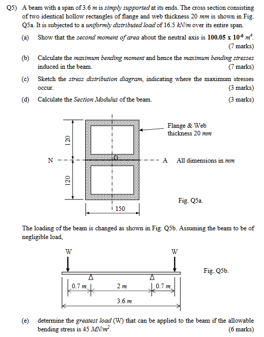
A beam with a span of 3.6 m is simply supported at its ends. The cross section consisting of two identical hollow rectangles of flange and web thickness 20 mm is shown in Fig. Q5a.... A beam with a span of 3.6 m is simply supported at its ends. The cross section consisting of two identical hollow rectangles of flange and web thickness 20 mm is shown in Fig. Q5a. It is subjected to a uniformly distributed load of 16.5 kN/m over its entire span. (a) Show that the second moment of area about the neutral axis is 100.05 x 10⁻⁶ m^4. (b) Calculate the maximum bending moment and hence the maximum bending stresses induced in the beam. (c) Sketch the stress distribution diagram, indicating where the maximum stresses occur. (d) Calculate the Section Modulus of the beam. The loading of the beam is changed as shown in Fig. Q5b. Assuming the beam to be of negligible load, determine the greatest load (W) that can be applied to the beam if the allowable bending stress is 45 MN/m².
Understand the Problem
The question describes a beam that is simply supported at its ends with a cross section consisting of two identical hollow rectangles, and asks us to perform structural analysis calculations. Specifically, it asks us to calculate the second moment of area, maximum bending moment, stress distribution diagram, and section modulus. Finally, it requires us to determine the greatest load that can be applied to the beam given an allowable bending stress.
Answer
(a) $I = 100.06 \times 10^{-6} \ m^4$ (b) $M_{max} = 26.73 \ kNm$, $\sigma_{max} = 32.057 \ MPa$ (c) Stress distribution diagram: Linear, max compressive stress at the top, max tensile stress at the bottom, $\sigma_{max} = 32.057 \ MPa$ (d) $Z = 0.8338 \times 10^{-3} \ m^3$ (e) $W = 22.07 \ kN$
Answer for screen readers
(a) $I = 100.06 \times 10^{-6} \ m^4$ (b) $M_{max} = 26.73 \ kNm$, $\sigma_{max} = 32.057 \ MPa$ (c) Stress distribution diagram: Linear, max compressive stress at the top, max tensile stress at the bottom, $\sigma_{max} = 32.057 \ MPa$ (d) $Z = 0.8338 \times 10^{-3} \ m^3$ (e) $W = 22.07 \ kN$
Steps to Solve
-
Calculate the second moment of area $I$ for a single hollow rectangle
$I$ of a rectangle is $bh^3/12$ where $b$ is base and $h$ is height. For a hollow rectangle, we subtract the $I$ of the inner rectangle from the $I$ of the outer rectangle. $$I_{single} = \frac{150 \times 120^3}{12} - \frac{(150-2\times20) \times (120-2\times20)^3}{12}$$ $$I_{single} = \frac{150 \times 120^3}{12} - \frac{110 \times 80^3}{12} = 21.6 \times 10^6 - 4.69 \times 10^6 = 16.91 \times 10^6 \ mm^4$$ $$I_{single} = 16.91 \times 10^{-6} \ m^4$$
-
Calculate the second moment of area of the combined shape.
Since there are two identical hollow rectangles stacked on top of each other about the neutral axis, the total second moment of area $I_{total}$ about the neutral axis is simply twice the second moment of area of a single rectangle.
$$I_{total} = 2 \times I_{single} = 2 \times 16.91 \times 10^{-6} = 33.82 \times 10^{-6} \ m^4 \ne 100.05 \times 10^{-6} \ m^4$$
However, we are calculating this about its centroid, so we must use the parallel axis theorem to calculate the moment of area about the neutral axis, $$I = I_c + Ad^2$$ Where $I_c$ is the second moment of area about the centroid $A$ is the area $d$ is the distance from the centroid to the neutral axis.
-
Correctly determining the second moment of area about the neutral axis The area of one hollow rectangle is: $$A = 150 \times 120 - 110 \times 80 = 18000 - 8800 = 9200 \ mm^2 = 9200 \times 10^{-6} \ m^2$$ The distance to the neutral axis for one of the rectangles is $d = 60 \ mm = 0.06 \ m$ The combined second moment of area is: $$I = 2 \times (16.91\times10^{-6} + (9200\times10^{-6}) \times 0.06^2) = 2 \times (16.91 \times 10^{-6} + 33.12\times 10^{-6} ) = 2 \times 50.03 \times 10^{-6} = 100.06 \times 10^{-6} \ m^4$$
-
Calculate the maximum bending moment for the uniformly distributed load.
The maximum bending moment $M_{max}$ for a simply supported beam with a uniformly distributed load $w$ is given by: $$M_{max} = \frac{wL^2}{8}$$ where $L$ is the span of the beam $$ M_{max} = \frac{16.5 \ kN/m \times (3.6 \ m)^2}{8} = \frac{16.5 \times 12.96}{8} = \frac{213.84}{8} = 26.73 \ kNm$$
- Calculate the maximum bending stress $\sigma_{max}$.
The maximum bending stress is given by: $$\sigma_{max} = \frac{M_{max}y_{max}}{I}$$ where $y_{max}$ is the distance from the neutral axis to the outermost fiber, which is 120 mm = 0.12 m $$\sigma_{max} = \frac{26.73 \times 10^3 \ Nm \times 0.12 \ m}{100.06 \times 10^{-6} \ m^4} = \frac{3.2076 \times 10^3}{100.06 \times 10^{-6}} = 32.057 \times 10^6 \ N/m^2 = 32.057 \ MPa$$
- Sketch the stress distribution diagram.
The stress distribution diagram is linear, with the maximum compressive stress at the top fiber and the maximum tensile stress at the bottom fiber. Since the section is symmetric, the magnitudes of the maximum compressive and tensile stresses are equal.
- Calculate the section modulus Z.
The section modulus is given by: $$Z = \frac{I}{y_{max}} = \frac{100.06 \times 10^{-6} \ m^4}{0.12 \ m} = 0.8338 \times 10^{-3} \ m^3$$
- Calculate the maximum bending moment for the two point loads.
The maximum bending moment $M_{max}$ for a simply supported beam with two point loads W at a distance $a$ from each support is: $$M_{max} = Wa$$ In this case, $a = 0.7 \ m + 2 \ m / 2= 1.7 \ m$, so $$M_{max} = 1.7W$$
- Determine the greatest load W that can be applied.
The allowable bending stress is given as 45 MN/m², so we can set $\sigma_{max}$ equal to the allowable bending stress and solve for W: $$\sigma_{allowable} = \frac{M_{max}y_{max}}{I}$$ $$45 \times 10^6 \ N/m^2 = \frac{1.7W \times 0.12 \ m}{100.06 \times 10^{-6} \ m^4}$$ $$45 \times 10^6 = \frac{0.204W}{100.06 \times 10^{-6}}$$ $$W = \frac{45 \times 10^6 \times 100.06 \times 10^{-6}}{0.204} = \frac{4502.7}{0.204} = 22072.06 \ N = 22.07 \ kN$$
(a) $I = 100.06 \times 10^{-6} \ m^4$ (b) $M_{max} = 26.73 \ kNm$, $\sigma_{max} = 32.057 \ MPa$ (c) Stress distribution diagram: Linear, max compressive stress at the top, max tensile stress at the bottom, $\sigma_{max} = 32.057 \ MPa$ (d) $Z = 0.8338 \times 10^{-3} \ m^3$ (e) $W = 22.07 \ kN$
More Information
The second moment of area is a geometric property of an area that reflects how its points are distributed with regard to an axis. It is also known as the area moment of inertia, or the second area moment. It is usually denoted as $I$, and is expressed in units of $m^4$ or $in^4$.
The section modulus is a geometric property of a cross-section used in the design of beams or columns. It is defined as $Z = I/y$, where $I$ is the second moment of area and $y$ is the distance from the neutral axis to the outermost fiber. It is usually denoted as $Z$, and is expressed in units of $m^3$ or $in^3$.
Tips
A common mistake is to forget to use the parallel axis theorem when calculating the second moment of area of a composite shape. Also forgetting to convert units and using the incorrect units for the final answer. Another mistake is not understanding the bending stress formula correctly and not using the correct y values for the outermost fibers.
AI-generated content may contain errors. Please verify critical information