Podcast
Questions and Answers
What are the two main types of transformers based on voltage transformation?
What are the two main types of transformers based on voltage transformation?
Step-up transformer and Step-down transformer.
In the equivalent circuit of a real transformer, what do R₁ and R₂ represent?
In the equivalent circuit of a real transformer, what do R₁ and R₂ represent?
Copper losses (resistance) in the primary and secondary windings, respectively.
What phenomena do X₁ and X₂ represent in the transformer equivalent circuit?
What phenomena do X₁ and X₂ represent in the transformer equivalent circuit?
Leakage reactance caused by leakage flux that escapes the core and passes through only one winding (primary or secondary).
What are the two components of core loss (Gc) in a transformer?
What are the two components of core loss (Gc) in a transformer?
What is hysteresis loss in a transformer core?
What is hysteresis loss in a transformer core?
In a typical distribution transformer secondary with terminals X₁, X₂, and X₃, which terminal is usually the center tap?
In a typical distribution transformer secondary with terminals X₁, X₂, and X₃, which terminal is usually the center tap?
In an AC circuit like a transformer, polarity is fixed, similar to a DC circuit.
In an AC circuit like a transformer, polarity is fixed, similar to a DC circuit.
What determines whether a transformer has additive or subtractive polarity?
What determines whether a transformer has additive or subtractive polarity?
If the secondary voltage adds to the primary voltage during a polarity test, the transformer has subtractive polarity.
If the secondary voltage adds to the primary voltage during a polarity test, the transformer has subtractive polarity.
According to IEEE standard C57.12.00-2015, a single-phase transformer rated 150 kVA with a primary voltage of 7200V must have subtractive polarity.
According to IEEE standard C57.12.00-2015, a single-phase transformer rated 150 kVA with a primary voltage of 7200V must have subtractive polarity.
What is the main purpose of performing an open-circuit test on a transformer?
What is the main purpose of performing an open-circuit test on a transformer?
What is measured during a short-circuit test on a transformer?
What is measured during a short-circuit test on a transformer?
How is the equivalent resistance ($R_{eq}$) determined from the short-circuit test results?
How is the equivalent resistance ($R_{eq}$) determined from the short-circuit test results?
What does transformer efficiency typically range between?
What does transformer efficiency typically range between?
Define voltage regulation in a transformer.
Define voltage regulation in a transformer.
A lower percentage voltage regulation indicates better transformer performance.
A lower percentage voltage regulation indicates better transformer performance.
What parameters can be determined using the data from both open-circuit and short-circuit tests?
What parameters can be determined using the data from both open-circuit and short-circuit tests?
Which transformer test is specifically used to find the variable losses (copper losses)?
Which transformer test is specifically used to find the variable losses (copper losses)?
Flashcards
Equivalent Circuit of a Transformer
Equivalent Circuit of a Transformer
A simplified representation capturing the key electrical characteristics, including winding and core losses, and magnetizing current.
Winding (Copper) Losses
Winding (Copper) Losses
Losses that occur in the primary and secondary windings of a transformer due to the resistance of the copper wire.
Hysteresis Losses
Hysteresis Losses
Energy needed to rearrange magnetic domains in the core; silicon steel minimizes this in AC applications.
Eddy Current Losses
Eddy Current Losses
Signup and view all the flashcards
Polarity
Polarity
Signup and view all the flashcards
Additive Polarity
Additive Polarity
Signup and view all the flashcards
Subtractive Polarity
Subtractive Polarity
Signup and view all the flashcards
Type Tests
Type Tests
Signup and view all the flashcards
Routine Tests
Routine Tests
Signup and view all the flashcards
Special Tests
Special Tests
Signup and view all the flashcards
Open Circuit Test
Open Circuit Test
Signup and view all the flashcards
Short Circuit Test
Short Circuit Test
Signup and view all the flashcards
Voltage Regulation
Voltage Regulation
Signup and view all the flashcards
Study Notes
Transformer Operation and Testing Objectives
- The objective is to grasp transformers and their equivalent circuits for practical use.
- Another objective is to learn how to determine a transformer's polarity.
- It's important to understand transformer tests, including open and short circuit tests.
- There is also an aim to learn about voltage regulation and its significance.
- The main goal is to interpret the results derived from transformer tests.
Introduction to Transformers
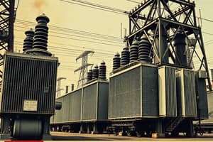
- Electrical engineers need to understand the parts of an electricity pole.
- Transformers are a key components to understand.
Equivalent Circuit of a Transformer
- The equivalent circuit represents the transformer's electrical traits, including winding and core losses.
- It also represents the magnetizing current.
Types of Transformers
- Transformers come in step-down and step-up types.
- Step-down transformers reduce voltage.
- Step-up transformers increase voltage.
Winding Losses (Copper Loss)
- Copper losses occur in the primary(R1) and secondary (R2) windings.
- Leakage flux (X1 and X2) escapes from the core through one winding.
Core Loss
- Core losses include Eddy current and Hysteresis losses.
- Eddy current losses result from resistive heating of the core.
- Hysteresis losses are energy lost rearranging magnetic domains in the core.
Actual Transformer Components
- Transformers have primary bushings (H1 & H2).
- Secondary bushings (X1, X2, X3) and core.
- They also have grounding straps.
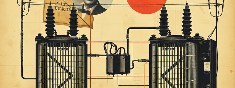
Actual Transformer Circuit Diagram
- Three-phase power lines (A, B, C) carry electricity to the transformer's primary windings from a power source.
- Primary terminals H1 and H2 connect the transformer to two phases, creating a magnetic field.
- This magnetic field induces voltage in the secondary windings through electromagnetic induction.
Secondary Side of Transformer
- The secondary side has a center-tapped winding with output points X1, X2, and X3.
- The center tap (X2) divides the secondary winding into two halves.
- The voltage between X1 and X3 is 240V, for appliances like air conditioners.
- Each winding half (X1 to X2, X3 to X2) delivers 120V for standard outlets.
- The center tap is neutral, grounded, creating a safe reference, stabilizing the 120V outputs.
- Single-phase transformers can be series or parallel.
- Transformers are AC devices without fixed polarity, needing comparative polarity markings when connected.
Polarity in Transformers
- Polarity refers to having two opposite points, determining current flow in electricity and magnets.
- In DC circuits, electrons flow neg to pos.
- In AC circuits, polarity switches causing current to change direction back and forth.
- Transformer polarity is either additive or subtractive.
Additive and Subtractive Polarity
- In additive polarity, X2 is left and X1 is right.
- In subtractive polarity, X1 is left and X2 is right.
- Transformer polarity depends on winding direction around the core.
- If primary and secondary coils are wound in opposite directions the polarity is additive.
- If they are wound in the same direction, it is subtractive.
AC Voltmeter Test for Polarity
- This test identifies transformer polarity before parallel connections.
- Incorrect polarity causes short circuits.
Additive and Subtractive Polarity Tests
- The secondary winding produces 24V from a 240V source because of the 10:1 ratio.
Additive Polarity Test
- X3 is connected to H1 using a jumper.
- The voltmeter measures 264V across H2 and X1.
- This additive polarity test shows the secondary voltage adds to the primary voltage
Subtractive Polarity Test
- X1 is connected to H1 using a jumper.
- The voltmeter measures 216V across H2 and X3.
- This subtractive polarity test shows the secondary voltage is 180° out of phase and opposes the primary voltage
Transformer Polarity Standards
- IEEE C57.12.00-2015 states single-phase transformers at 200 kVA or below and 8,660 volts or below must have additive polarity.
- All other single-phase transformers have subtractive polarity.
- Transformer polarity can be identified on the nameplate.
- The example transformer has a 15 kVA rating and a primary voltage of 7200V.
- It has additive polarity, meeting qualifications for an additive polarity transformer.
Transformer Testing
- Transformer testing checks if a transformer is working properly.
- Various tests measure performance and efficiency, guiding corrective actions.
- Transformer testing includes Type, Routine, Special, and Pre-Commission Tests.
Type Tests
- Type Tests confirm the basic design criteria.
- It includes winding resistance, transformer ratio, and vector group tests.
- The measurements include impedance voltage/short circuit impedance and load loss (short circuit test).
- There is also measurement of no-load loss and current (open circuit test).
- Insulation resistance and dielectric tests are conducted.
- Temperature rise tests and vacuum tests are also completed.
Routine Tests
- Routine Tests confirm performance of each unit in a production lot.
- These include winding resistance, transformer ratio, and vector group tests.
- The measurements include impedance voltage/short circuit impedance and load loss (short circuit test).
- There is also measurement of no-load loss and current (open circuit test).
- Insulation resistance and dielectric tests are conducted.
- There is further testing on on-load tap-changers and oil pressure.
Special Tests
- Special Tests are done under specific circumstances, not standard procedures.
Pre-Commissioning Tests
- Pre-Commissioning Tests ensure correct installation and good working condition.
- Two key tests covered are the Open Circuit Test and Short Circuit Test.
Open Circuit Test
- The Open Circuit Test finds shunt parameters of the transformer's equivalent circuit.
- The rated voltage is applied to one winding while keeping the other open.
- A voltmeter, wattmeter, and ammeter are connected to the LV side.
- A variac increases voltage until the voltmeter reads the rated LV voltage.
- Voltmeter, ammeter, and wattmeter readings are then recorded.
Open Circuit Test Computations
- Parameters like Pc can be computed using measured values.
- The no-load power factor (cos θ0) is computed using PC.
- Magnetizing and core loss are calculated using a vector diagram.
- Shunt parameters RC and Xm are computed from measured values.
- Calculations are often done on the LV side.
- If required, calculated values can be converted to the HV side.
Short Circuit Test
- The Short Circuit Test measures load loss and leakage impedance.
- A voltage is applied to the HV winding to circulate rated currents through both windings.
- LV winding is typically short-circuited for this test.
- The applied voltage is tuned to achieve full load current in both windings.
Short Circuit Test Computations
- Parameters like Req1, Xeq1, and Zeq1 are derived from measured power, voltage, and current.
- Transformer efficiency typically ranges from 95% to 99%.
- Large low-loss transformers can achieve efficiency as high as 99.7%.
- The efficiency is determined using losses measured via open-circuit and short-circuit tests.
Example Transformer Test Results
- A 50kVA, 250/500V, 50Hz single-phase transformer's test results are used to determine equivalent circuit parameters.
Voltage Regulation
- Voltage regulation measures percentage voltage rise at the transformer's terminals when the load is removed.
- It reflects the change in secondary voltage as the load varies, keeping primary voltage constant.
- Lower voltage regulation means better transformer performance.
- The general formula uses Vno load and Vfull load to calculate %VR.
Why Lower Voltage Regulation is Better
- Minimal voltage drop under load due to lower voltage regulation.
- Better efficiency because it indicates lower internal losses.
- Stable operation, so equipment works better with consistent voltage.
Importance of Voltage Regulation
- Voltage regulation stabilizes the voltage even with load changes.
Voltage Regulation Example
- Poor voltage regulation of 230V rated transformer reduces voltage to 190V under load.
- The voltage instability can cause device malfunction.
Learnings from Tests
- Open/short circuit tests determine transformer equivalent circuit parameters, efficiency, and voltage regulation.
Open Circuit Test Use
- Find core loss or constant loss at rated voltage and frequency.
- It helps to find no-load branch parameters.
- The test determines turns ratio.
Short Circuit Test Use
- Short Circuit Test can determine equivalent resistance and reactance.
- It can also find variable losses (copper loss).
- Using short circuit test data, voltage regulation can be determined.
Studying That Suits You
Use AI to generate personalized quizzes and flashcards to suit your learning preferences.