Podcast
Questions and Answers
How can the balance of ampere-turns between the primary and secondary circuits be translated into apparent power balance in an ideal transformer?
How can the balance of ampere-turns between the primary and secondary circuits be translated into apparent power balance in an ideal transformer?
Ip Ep = Is Es
What is the equation representing the balance of ampere-turns between the primary and secondary circuits in an ideal transformer on load?
What is the equation representing the balance of ampere-turns between the primary and secondary circuits in an ideal transformer on load?
IpNp = IsNs
What is the relationship between the primary and secondary power factors in a transformer on full-load?
What is the relationship between the primary and secondary power factors in a transformer on full-load?
They are always nearly the same
What is the term used to refer to the magnitude of complex power in a transformer?
What is the term used to refer to the magnitude of complex power in a transformer?
In terms of complex power, what is the relationship between the power supplied to the primary winding and the power delivered to the load by the secondary winding in an ideal transformer?
In terms of complex power, what is the relationship between the power supplied to the primary winding and the power delivered to the load by the secondary winding in an ideal transformer?
What condition implies that the primary and secondary power factors are nearly the same on full-load in a transformer?
What condition implies that the primary and secondary power factors are nearly the same on full-load in a transformer?
Who built the first practical modern transformer in 1885?
Who built the first practical modern transformer in 1885?
What is the alternating flux produced at the primary voltage denoted by?
What is the alternating flux produced at the primary voltage denoted by?
What does the transformer E.M.F. equation describe?
What does the transformer E.M.F. equation describe?
In the transformer E.M.F. equation, what does Φ represent?
In the transformer E.M.F. equation, what does Φ represent?
What is the core made up of in the first practical modern transformer built by William Stanley?
What is the core made up of in the first practical modern transformer built by William Stanley?
Why is only one high-voltage insulator and lightning arrester needed in the self-protected distribution transformer?
Why is only one high-voltage insulator and lightning arrester needed in the self-protected distribution transformer?
What is the primary current like when the secondary winding of the transformer is on open-circuit?
What is the primary current like when the secondary winding of the transformer is on open-circuit?
What is the usual percentage of the full-load primary current that the magnetising current represents?
What is the usual percentage of the full-load primary current that the magnetising current represents?
When a load is connected across the secondary terminals, what effect does the secondary current produce?
When a load is connected across the secondary terminals, what effect does the secondary current produce?
What happens to the e.m.f. induced in the primary winding when a load is connected to the transformer?
What happens to the e.m.f. induced in the primary winding when a load is connected to the transformer?
How does the primary current change when the e.m.f. induced in the primary winding is reduced?
How does the primary current change when the e.m.f. induced in the primary winding is reduced?
What is the function of the current produced in the secondary winding when a load is connected?
What is the function of the current produced in the secondary winding when a load is connected?
Explain why the appearance of IsNs due to the secondary load current must be counter-balanced in a transformer.
Explain why the appearance of IsNs due to the secondary load current must be counter-balanced in a transformer.
What is the significance of the rate of EsIs in a transformer and how is it related to the rate of EpIp?
What is the significance of the rate of EsIs in a transformer and how is it related to the rate of EpIp?
Why is it important to have equal and opposite currents in the primary and secondary of a transformer?
Why is it important to have equal and opposite currents in the primary and secondary of a transformer?
How does the conservation of energy principle apply to the operation of an ideal transformer?
How does the conservation of energy principle apply to the operation of an ideal transformer?
Explain the relationship between VsIs and VpIp in the context of energy transfer in a transformer.
Explain the relationship between VsIs and VpIp in the context of energy transfer in a transformer.
What role does the equal and opposite energy introduction rate EpIp play in the operation of a transformer?
What role does the equal and opposite energy introduction rate EpIp play in the operation of a transformer?
What are the conditions in an ideal transformer where equation 4.6 holds exactly?
What are the conditions in an ideal transformer where equation 4.6 holds exactly?
Describe the phase relations in an ideal transformer according to Figure 4.3(c).
Describe the phase relations in an ideal transformer according to Figure 4.3(c).
What determines the phase and magnitude of the secondary current in an ideal transformer?
What determines the phase and magnitude of the secondary current in an ideal transformer?
What is the relationship between secondary m.m.f. and primary m.m.f. in an ideal transformer?
What is the relationship between secondary m.m.f. and primary m.m.f. in an ideal transformer?
Explain the stability conditions in an ideal transformer represented in Figure 4.3(c).
Explain the stability conditions in an ideal transformer represented in Figure 4.3(c).
What are the implications of having no resistance and leakage reactance drops in an ideal transformer?
What are the implications of having no resistance and leakage reactance drops in an ideal transformer?
Flashcards
Ampere-turns balance (ideal transformer)
Ampere-turns balance (ideal transformer)
The primary and secondary ampere-turns are equal and opposite in an ideal transformer, ensuring power balance.
Transformer equation
Transformer equation
IpNp = IsNs ,balancing ampere-turns in an ideal transformer.
Power factors (full-load)
Power factors (full-load)
Primary and secondary power factors are nearly the same in a transformer on full load.
Apparent power
Apparent power
Signup and view all the flashcards
Transformer power balance
Transformer power balance
Signup and view all the flashcards
Ideal transformer condition
Ideal transformer condition
Signup and view all the flashcards
William Stanley
William Stanley
Signup and view all the flashcards
Φ (transformer)
Φ (transformer)
Signup and view all the flashcards
Transformer EMF equation
Transformer EMF equation
Signup and view all the flashcards
Transformer core material
Transformer core material
Signup and view all the flashcards
Self-protected distribution transformer
Self-protected distribution transformer
Signup and view all the flashcards
Open-circuit primary current
Open-circuit primary current
Signup and view all the flashcards
Magnetising current
Magnetising current
Signup and view all the flashcards
Secondary current effect (load)
Secondary current effect (load)
Signup and view all the flashcards
Primary EMF change (load)
Primary EMF change (load)
Signup and view all the flashcards
Secondary current function (load)
Secondary current function (load)
Signup and view all the flashcards
Conserving energy principle (transformers)
Conserving energy principle (transformers)
Signup and view all the flashcards
Energy transfer balance (transformer)
Energy transfer balance (transformer)
Signup and view all the flashcards
Primary & secondary current balance
Primary & secondary current balance
Signup and view all the flashcards
Ideal transformer equations
Ideal transformer equations
Signup and view all the flashcards
Stability conditions (ideal transformer)
Stability conditions (ideal transformer)
Signup and view all the flashcards
Resistance and leakage reactance (ideal transformers)
Resistance and leakage reactance (ideal transformers)
Signup and view all the flashcards
Phase relations (ideal transformer)
Phase relations (ideal transformer)
Signup and view all the flashcards
Secondary current determination
Secondary current determination
Signup and view all the flashcards
Primary and secondary m.m.f.
Primary and secondary m.m.f.
Signup and view all the flashcards
Ideal transformer stability
Ideal transformer stability
Signup and view all the flashcards
Study Notes
Ideal Transformer
- An ideal transformer on load has a demagnetizing flux, Φs, which is neutralized by the increase in primary ampere-turns (IpNp).
- The primary ampere-turns (IpNp) and secondary ampere-turns (IsNs) are nearly equal, resulting in a magnetic field (m.m.f) balance: IpNp = IsNs.
Transformer Equations
- Equation 4.5: IpNp = IsNs
- Equation 4.6: Ep/Es = Vp/Vs = Np/Ns
- Equation 4.7: IpEp = IsEs (apparent power balance)
- Equation 4.7(b): IpVp = IsVs* (complex power balance)
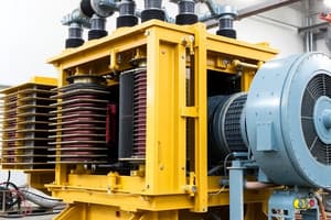
Transformer Construction
- Core-type transformer: core surrounds the windings
- Shell-type transformer: windings surround the core
- Figure 2.2(a) and 2.2(b): shell-type transformer construction
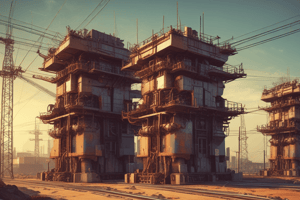
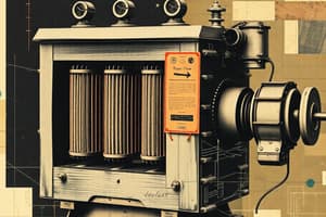
- Figure 2.3(a): cutaway view of self-protected distribution transformer
- Figure 2.3(b): typical shell-type transformer
- Figure 2.3(c): the first practical modern transformer built by William Stanley in 1885
Transformer E.M.F. Equation
- Equation 3.1(a): Φ = Φmsin2πft (alternating flux produced at the primary voltage)
- Equation 4.3(b): Ep/Es = Np/Ns = α
- Equation 4.4: Ep/Es = Vp/Vs = Np/Ns
Ideal Transformer on Load
- When a load is connected, the secondary current produces a demagnetizing effect, reducing the flux and e.m.f. induced in the primary winding.
- The primary current increases to counterbalance the demagnetizing effect, resulting in a magnetic field (m.m.f) balance.
Equivalent Circuit and Phasor Diagrams
- In an ideal transformer, there are no voltage drops in resistance or leakage reactance, and no core loss.
- Equation 4.6 holds exactly, and the phase relations are simple: Vp = Ep, Vs = Es, and Ip = Is.
- The secondary m.m.f. is IsNs, and the primary m.m.f. is IpNp, which is equal and opposite to the secondary m.m.f.
Studying That Suits You
Use AI to generate personalized quizzes and flashcards to suit your learning preferences.