Podcast
Questions and Answers
What is the preferred temperature range for a soldering iron tip in the context of the provided content?
What is the preferred temperature range for a soldering iron tip in the context of the provided content?
- 320 oC
- 260 oC
- 260 oC to 320 oC
- 240 oC to 280 oC (correct)
According to the provided content, what is the proper procedure for maintaining the soldering iron tip during periods of non-use?
According to the provided content, what is the proper procedure for maintaining the soldering iron tip during periods of non-use?
- Clean the tip using a metal wool, apply a small amount of solder to the tip, then place the iron in the stand.
- Place the iron in the stand, clean the tip using a wet sponge, then apply a small amount of solder to the tip.
- Clean the tip using a wet sponge, apply a small amount of solder to the tip, then place the iron in the stand. (correct)
- Apply a small amount of solder to the tip, clean the tip using a wet sponge, then place the iron in the stand.
What is the purpose of the SPI (Solder Paste Inspection) in SMT assembly?
What is the purpose of the SPI (Solder Paste Inspection) in SMT assembly?
- To verify the quality of the solder paste printing process. (correct)
- To ensure the correct placement of components on the PCB.
- To determine the x-ray visibility of soldered joints.
- To inspect the soldered joints for defects.
Which of the following steps are NOT part of the SMT assembly procedure outlined in the content?
Which of the following steps are NOT part of the SMT assembly procedure outlined in the content?
Which of the following is NOT a factor considered during incoming component inspection in the SMT assembly procedure as outlined in the content?
Which of the following is NOT a factor considered during incoming component inspection in the SMT assembly procedure as outlined in the content?
What is a common cause of 'Disturbed Solder'?
What is a common cause of 'Disturbed Solder'?
Which of the following is NOT a characteristic of 'Excess Solder' ?
Which of the following is NOT a characteristic of 'Excess Solder' ?
Which of the following is a potential consequence of 'Cold Solder'?
Which of the following is a potential consequence of 'Cold Solder'?
What is the recommended solution for 'Blow Holes' in a solder joint?
What is the recommended solution for 'Blow Holes' in a solder joint?
What is the appearance of a 'Disturbed Solder' joint?
What is the appearance of a 'Disturbed Solder' joint?
What's the recommended action to correct a 'Cold Solder' joint?
What's the recommended action to correct a 'Cold Solder' joint?
What is a primary cause for 'Excess Solder' in a joint?
What is a primary cause for 'Excess Solder' in a joint?
What is the primary characteristic of a 'Cold Solder' joint?
What is the primary characteristic of a 'Cold Solder' joint?
Which of the following is NOT a potential cause for the 'Head-in-Pillow' (HIP) defect?
Which of the following is NOT a potential cause for the 'Head-in-Pillow' (HIP) defect?
What is the recommended solution to address 'Open BGA Joint' defects?
What is the recommended solution to address 'Open BGA Joint' defects?
What is the recommended solution for addressing 'Cracked SMD Capacitor' defects?
What is the recommended solution for addressing 'Cracked SMD Capacitor' defects?
Which of these defects primarily occurs due to issues during the preheating and soaking stage of the reflow profile?
Which of these defects primarily occurs due to issues during the preheating and soaking stage of the reflow profile?
How can one address 'Poor Solderability' problems during the soldering process?
How can one address 'Poor Solderability' problems during the soldering process?
What is the primary cause of 'Tombstone Components' defect in the soldering process?
What is the primary cause of 'Tombstone Components' defect in the soldering process?
Which of the following defect is directly related to the heating rate of the reflow profile?
Which of the following defect is directly related to the heating rate of the reflow profile?
Which of the following solutions is applicable for preventing 'Solder Balls' around SMD components?
Which of the following solutions is applicable for preventing 'Solder Balls' around SMD components?
What is the primary purpose of the Ionic Contamination Test?
What is the primary purpose of the Ionic Contamination Test?
What is the acceptable limit for ionic contamination, expressed as NaCl equivalent?
What is the acceptable limit for ionic contamination, expressed as NaCl equivalent?
What is the typical duration for the rinsing process during the Ionic Contamination Test?
What is the typical duration for the rinsing process during the Ionic Contamination Test?
What is the recommended cleaning level for the machine solvent regeneration prior to immersing the electronic assembly?
What is the recommended cleaning level for the machine solvent regeneration prior to immersing the electronic assembly?
What is the primary purpose of the baking process after the rinsing step?
What is the primary purpose of the baking process after the rinsing step?
What is the main purpose of the 'Soak' zone in an SMT reflow profile?
What is the main purpose of the 'Soak' zone in an SMT reflow profile?
Which of the following factors would NOT directly affect the reflow profile?
Which of the following factors would NOT directly affect the reflow profile?
During which step of the SMT process is the 'Component placement verification' performed?
During which step of the SMT process is the 'Component placement verification' performed?
What is the purpose of the 'Preheat' zone in a reflow profile?
What is the purpose of the 'Preheat' zone in a reflow profile?
What type of components are typically removed during the 'Removing SMT' stage?
What type of components are typically removed during the 'Removing SMT' stage?
Which of the following tasks is performed BEFORE the 'Master data preparation' step in the SMT process?
Which of the following tasks is performed BEFORE the 'Master data preparation' step in the SMT process?
What is the significance of the 'Thermal Profile run & verification' step in the SMT process?
What is the significance of the 'Thermal Profile run & verification' step in the SMT process?
Which of these tasks is NOT typically performed during the 'Cleaning & Inspection' stage in the SMT process?
Which of these tasks is NOT typically performed during the 'Cleaning & Inspection' stage in the SMT process?
What is the primary reason for insufficient or no solder during the solder paste printing process?
What is the primary reason for insufficient or no solder during the solder paste printing process?
Why is it important to ensure good wetting of surfaces during the soldering process?
Why is it important to ensure good wetting of surfaces during the soldering process?
What is the purpose of the cold sump and vapor zone in the vapor degreasing cleaning method?
What is the purpose of the cold sump and vapor zone in the vapor degreasing cleaning method?
What is the main difference between manual cleaning and vapor degreasing methods?
What is the main difference between manual cleaning and vapor degreasing methods?
Which of the following is NOT a characteristic of a good solder joint?
Which of the following is NOT a characteristic of a good solder joint?
During component placement, if a feeder problem causes parts to be flipped onto their side, what should you do?
During component placement, if a feeder problem causes parts to be flipped onto their side, what should you do?
What is the purpose of inspecting the solder paste print before component placement?
What is the purpose of inspecting the solder paste print before component placement?
What is the recommended action to address insufficient solder paste during the printing process?
What is the recommended action to address insufficient solder paste during the printing process?
Flashcards
Soldering Iron Temperature Range
Soldering Iron Temperature Range
Recommended tip temperature for soldering iron is 240°C to 280°C, with a preferred temperature of 260°C.
Tip Care Procedure
Tip Care Procedure
The tip should be tinned and cleaned with a wet sponge or metal wool during use and after idling periods.
Idling Procedures for Soldering Iron
Idling Procedures for Soldering Iron
During non-use, wipe the bit, apply solder, and place the iron in its stand before the next use.
Solder Paste Printing
Solder Paste Printing
Signup and view all the flashcards
Inspection Techniques in SMT
Inspection Techniques in SMT
Signup and view all the flashcards
Stencil Procurement
Stencil Procurement
Signup and view all the flashcards
Reflow Soldering
Reflow Soldering
Signup and view all the flashcards
PCB Material
PCB Material
Signup and view all the flashcards
Reflow Profile Zones
Reflow Profile Zones
Signup and view all the flashcards
Component Placement Verification
Component Placement Verification
Signup and view all the flashcards
Solder Paste Inspection
Solder Paste Inspection
Signup and view all the flashcards
Factors Affecting Reflow Profile
Factors Affecting Reflow Profile
Signup and view all the flashcards
Master Data Preparation
Master Data Preparation
Signup and view all the flashcards
Solder Coverage
Solder Coverage
Signup and view all the flashcards
Excess Solder
Excess Solder
Signup and view all the flashcards
Cold Solder Joint
Cold Solder Joint
Signup and view all the flashcards
Wetting Issues
Wetting Issues
Signup and view all the flashcards
Solder Balls
Solder Balls
Signup and view all the flashcards
Heating Rate of Reflow Profile
Heating Rate of Reflow Profile
Signup and view all the flashcards
Disturbed Solder
Disturbed Solder
Signup and view all the flashcards
Reheat Correction
Reheat Correction
Signup and view all the flashcards
Poor Solderability
Poor Solderability
Signup and view all the flashcards
Blow Holes
Blow Holes
Signup and view all the flashcards
Cracked SMD Capacitor
Cracked SMD Capacitor
Signup and view all the flashcards
Head-in-Pillow (HIP)
Head-in-Pillow (HIP)
Signup and view all the flashcards
Flux Role
Flux Role
Signup and view all the flashcards
Open BGA Joint
Open BGA Joint
Signup and view all the flashcards
Tombstone Components
Tombstone Components
Signup and view all the flashcards
Reduce Heating Rate
Reduce Heating Rate
Signup and view all the flashcards
IONIC CONTAMINATION TEST
IONIC CONTAMINATION TEST
Signup and view all the flashcards
Conductivity of Solvent Extracted (ROSE/SEC)
Conductivity of Solvent Extracted (ROSE/SEC)
Signup and view all the flashcards
Acceptance Limit
Acceptance Limit
Signup and view all the flashcards
Test Duration
Test Duration
Signup and view all the flashcards
Rinsing Process
Rinsing Process
Signup and view all the flashcards
Pickup Error
Pickup Error
Signup and view all the flashcards
Solder Insufficiency
Solder Insufficiency
Signup and view all the flashcards
Good Solder Joint Characteristics
Good Solder Joint Characteristics
Signup and view all the flashcards
Manual Cleaning Method
Manual Cleaning Method
Signup and view all the flashcards
Vapour Degreasing
Vapour Degreasing
Signup and view all the flashcards
Vision System Adjustment
Vision System Adjustment
Signup and view all the flashcards
Solder Paste Replenishment
Solder Paste Replenishment
Signup and view all the flashcards
Study Notes
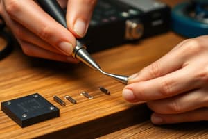
Soldering Materials, Process & Tools
- Soldering is a process of joining two parent metals using a third material (filler) with a lower melting temperature.
- Soldering creates a metallurgical bond at temperatures below 600°F (315°C).
- Soldering materials include solder alloys, fluxes, base metals, and cleaning solvents. Specific MIL and IPC specifications exist for these.
Uniqueness of Space Missions
- Space missions demand high reliability due to the expense of mission failure.
- The design complexity of space missions is multi-disciplinary, and involves weight, volume, power, and thermal limitations.
- Single-shot, non-repairable systems are employed.
- Missions are often unattended with no on-site repair.
- Space conditions, including vibrations, extreme temperatures, vacuum, outgassing, and radiation, need to be considered during design and operation.
Difference between Commercial and Space Hardware
- Space hardware needs to withstand harsh space conditions (extreme temperatures, radiation, vacuum, shock, and vibration) and maintain high reliability.
- Space hardware cannot be repaired in the field.
Quality & Reliability
- Quality is the degree to which a product meets customer specifications at the start of its life.
- Reliability is the probability that a product/system will adequately perform its intended function under stated operating conditions for a specified time without failure.
- Factors like quality over time, dependability, durability, probability, and availability influence reliability.
Space Missions
- Space missions are highly sensitive to reliability concerns.
- The loss of a mission results in significant financial and reputational damage, as it is a matter of national pride.
- Significant investments are made in each mission.
- Uninterrupted service and ground support equipment are required.
- Replacement times are typically long (18-24 months).
- Space missions demand zero defects.
How Reliability of Space Systems is Ensured
- Designs utilize sufficient safety margins.
- High-quality components and space-proven materials and consumables are critical.
- Controlled environment conditions during fabrication and operation are necessary.
- Skilled, qualified personnel and workmanship are essential factors.
- Systems are tested under simulated space conditions (ground handling, launch, and orbital operations) to evaluate flightworthiness.
- Reliability assessments are conducted.
- Redundancy in critical subsystems is implemented.
Reliability in Space Systems
- Reliability involves quality measures across the project life cycle phases (design, realization, subsystems performance, launch, orbital, performance).
- Continuous quality improvements are required throughout the process.
Solder Joint Quality & Reliability
- Controlled environmental conditions are essential for high-quality solder joints.
- High-quality, space-proven materials must be selected and controlled.
- Processes must be appropriately qualified for space-level requirements.
- Skilled and trained personnel are critical for the solder joint and overall workmanship.
- Maintaining zero defects is crucial.
Controlled Environmental Conditions
- Cleanliness must meet class 100,000 standards.
- Temperature control is maintained at 22 ± 3°C.
- Relative humidity is controlled at 55 ± 5%RH.
- Lighting requirements are 1100 lumens/sq.m.
- ESD protection methods and storage, handling, and transportation procedures are essential.
Cleanliness (for electronic assembly)
- Aiming to avoid foreign particles that compromise quality, performance, or reliability of electronic assemblies.
- Classifications of 100,000 and 10,000 for different electronic applications are used. (refer to documents for the specifications relating to particle size).
Temperature, Humidity & Lighting
- Temperature control prevents corrosion of metallic components in humid environments.
- Specifications are 22 ± 3°C.
- Proper relative humidity control (55-60% RH) balances issues associated with ESD and corrosion.
- Lighting requirements are 1100 lumens/sq.m.
Types of ESD Failures & ESD Precautions
- ESD-related failures fall under catastrophic, parametric, or latent categories.
- ESD protection necessitates prevention of charge generation, dissipation of generated charge, charge neutralization, and use of shielding.
Materials Selection and Control
- Heritage of materials is critically assessed when selecting and controlling materials for space applications.
- Material qualification, certification, and incoming inspections, along with traceability requirements, are applied to components.
Process Control
- Defined, qualified processes (work instructions and PID, checklists, fabrication documentation) and measurement/inspections ensure quality in space component processes.
- Evaluation and control of defects and management of nonconformities (NC) are necessary.
Definition of Soldering
- Soldering is the joining of two parent metals using a third, filler material with a lower melting point.
- Soldering is the process of creating a metallurgical bond at temperatures below 600°F (315°C).
Solder Joint Design and Workmanship
- Solder joints must conform to design specifications for electrical conductivity, mechanical strength, heat dissipation, ease of manufacturing, simplicity of repair, and visual inspectability.
Basic Design Concepts for Reliable Connections and to Avoid Solder Joint Failure
- Stress relief and solder-joint reinforcement are used.
- Mismatch in thermal expansion coefficients is minimized, and materials/processes that form brittle intermetallics are avoided.
- Design allows for inspection.
Fabrication Materials
- Solder alloy, flux, base metal, and cleaning solvents. Detailed parameters and specifications (identified by MIL and IPC) are utilized.
Types of Solder Alloys
- Solder alloys are categorized by their intended use (wave soldering, PCB/connector wiring, reflow soldering, solderability testing).
Types of Solder Alloy (by Composition)
- Soft solders (Sn 63/37 Pb or Sn 62/2 Ag/36 Pb) have a melting point of 183°C.
- Sn 62/2 Ag/36 Pb has a lower melting point of 179°C.
- Hard solders (e.g., HMP solder Pb 95.5-4.5) have melting points around 308 °C.
Properties of Tin & Lead
- Tin: Bright, silver-white, lustrous, resists atmospheric corrosion.
- Lead: Bluish-grey, dull-grey appearance when exposed to air, malleable and ductile.
- Differences exist in thermal and fluid properties.
Eutectic Solder Alloy (Sn63Pb37)
- Good mechanical strength (140.5 kg/cm², 43.0, and 37.0 MPa).
- Anneals at 22°C with a CTE matching copper at -24.5 ppm/°C and a low resistance of 2-3 mΩ.
- Low melting temperature (183°C).
Eutectic Solder Alloy (Sn62Ag2Pb36)
- Good mechanical strength (140.5 kg/cm², 48.3, and 52.0 MPa).
- Anneals at 22°C with a CTE matching copper at -27 ppm/°C and a low resistance of 2-3 mΩ.
- Low melting temperature (179°C).
Solder Alloy Comparison (Sn63Pb37 & Sn62Ag2Pb36)
- Detailed comparison of characteristics (composition, melting point, density, thermal & electrical conductivity, Young's Modulus, tensile strength, elongation, etc.) is given.
Phase Diagram (Tin-Lead)
- Provides a visual representation of phase transitions for tin-lead alloys.
Soldering Iron Temperature Selection Guide
- Selecting the correct soldering iron temperature range is crucial (approximately melting point + 60-100°C). Using 240°C to 280°C.
Fabrication Materials (Flux)
- Flux is a chemically active compound that removes surface oxidation and promotes intermetallic layer formation between the solder and base.
Function of Flux
- Flux acts as a cleaning agent, catalyst, triggers/promotes a process, avoids oxidation of base metals, and promotes solder wetting.
Properties of Flux
- Resisting evaporation or breakdown at soldering temperatures (170-180°C).
- Deactivation temperature (330°C) and chemically inert, non-corrosive flux residues (at the end of the process).
Types of Fluxes (e.g., Inorganic, Organic: Rosin, RMA, RA).
- Specific composition and activation levels (low, moderate, high) of various types of flux.
Fabrication Materials (Base Metal)
- Base metal requirements, for example, good solderability of patterned pads and component leads.
Cleaning Solvents (TT-1-735)
- Cleaning solvents remove dust, corrosion, fingerprints, grease, and flux residues. Also, they shall dissolve oil, grease, dirt, and flux residues.
Features of Cleaning Solvents
- Solvents needs to dissolve grease, dirt, flux residues, and both ionic and non-ionic contaminants.
- Proper evaporation at room temperature is essential, and they should not erase component markings.
- The cleaning solvents need to be environmentally safe (thermal and chemical).
Types of Solvents (Polar, Non-polar, Bipolar, Azeotropic)
- Polar solvents dissolve polar compounds.
- Non-polar solvents dissolve non-polar compounds.
- Bipolar solvents dissolve both polar and non-polar compounds..
- Azeotropic solvents form mixtures that vaporize and condense at constant compositions.
Solder Joint Formation - Pictorial Presentation
- Illustrative diagrams of solder joint formation (vacuum, air-exposed, tarnished, clean) are provided.
Wetting
- Solder wetting is a critical aspect of the soldering process.
- Molten solder flows into surface imperfections and penetrates the interface to adhere.
- The chemical reaction between the solder and substrate creates a metallurgical bond.
Schematic of Thermodynamic Equilibrium in Wetting
- A diagram displays different wetting scenarios (total, partial, complete/non-wetting). Wetting angles (θ) provide information about the wetting process in the diagram). This is controlled by surface energies.
Soldering Stations (e.g., MIL-STD-2000A, ANSI/ESD S20.20-2021)
- Standards, specifications, and parameters detailing soldering station requirements and quality.
Important Specifications of Soldering Stations
- Included are considerations like heater/cartridge technology, temperature range/stability, display type, and ESD protection specifications.
General Purpose Tips (for soldering)
- List of different soldering tip types (e.g., conical, conical bent, chisel, chisel bent, bevel, bevel bent).
Component Soldering (Procedure)
- A description of the component soldering steps including surface and lead preparation, component placement, heating, solder application, cleaning, and inspection.
Advantages of Soldering at Lower Temperatures
- Longer tip lifespan due to reduced oxidation.
- Improved tip wettability and heat transfer efficiency.
- Flux activation occurs without direct burning of the tip, leading to better wettability.
- Reduced risk of damage to components and PCBs.
- Improved process quality (fewer rework issues, scraps).
Maintenance of Soldering Iron
- Instructions are included on checking the bit and grounding condition (replace if necessary), setting appropriate tip temperature ranges, cleaning the tool, and performing maintenance.
SMT Assembly Procedure
- Steps in the SMT assembly procedure are presented, including material preparation, solder paste printing/inspection, component pick-and-place/inspection, reflow soldering/cleaning, assembly inspection, and rework activities.
Solder Paste Printer, SMT Pick & Place, SMT Reflow Oven, X-ray Inspection, SMT Rework Station
- Description of each machine and its role in the SMT assembly process.
Factors Affecting Reflow Profile
- Key parameters to consider when establishing the reflow profile, including solder paste type, PCB material/thickness, number of layers, amount of copper, number of surface-mount components, and type of surface-mount components.
SMT Reflow Profile
- A graphical representation of a typical reflow profile with key temperature/time zones for pre-heating, soaking, reflowing, and cooling. Also, specifications including ΔT (temperature difference), Melting point, and time (seconds).
SMT Reflow Profile (phases)
- Discussion of the pre-heating, soaking, reflowing, and cooling phases.
Solder Joint Inspection
- Key aspects of solder joint inspection (visual inspection, non-destructive testing (e.g. X-ray), and destructive testing (e.g., metallographic cross-section, bond pull test)) during the inspection and testing steps.
Good Solder Joints Characteristics
- Criteria, including smooth bright/shiny surface, concave fillet, appropriate solder quantity, 5-20 degree dihedral angle, and good surface wetting, and conductor visibility during inspection.
Solder Fatigue Through Hole vs. Surface Mount
- Drawings illustrating the possible solder joints fatigue through-hole (THT) and surface-mount (SMT) components
Defects in Through-hole Soldering Process
- A variety of through-hole soldering defects (e.g., insufficient/excess solder, pin holes, blow holes, de-wetted, over-heated, cold,/rosin, disturbed, cracks) are shown. Images illustrate the defects.
Defects Cause, Effect & Correction (THT)
- Identification of probable causes for through-hole soldering defects, their effects, and corrective actions.
Defects in SMT Soldering Process
- Common solder joint defects in surface-mount technology (SMT): solder balls, poor solderability, cracked capacitor, open BGA joint, tombstone components, solder voiding, billboard parts, or insufficient/no solder.
Defects Cause, Effect & Correction (SMT)
- Examination identifies potential causes of SMT defects, their effects, and suitable corrective actions.
Cleaning Process (Manual)
- Procedure for manual cleaning of PCBs and components after the soldering process, including the use of IPA.
Vapor Degreasing Cleaning Method
- A method for cleaning highly dense wired PCBs utilizing IPA and a vapor degreasing system.
Ionic Contamination Test
- Used on electronic assemblies/components to assess cleanliness after SMT processes.
- Methods used on functional testing or coating of components.
Ionic Contamination Procedure
- Detailed procedure for examining cleanliness test, including steps like area calculation, machine operation, immersion, testing, and evaluation, as well as acceptance criteria.
Applicable Documents (for soldering processes)
- A listing of documents/standards that are important for the fabrication, packaging, and testing of electronics in accordance with the specifications listed.
Thank You
Studying That Suits You
Use AI to generate personalized quizzes and flashcards to suit your learning preferences.