Podcast
Questions and Answers
What color indicates that a stop signal is at 'ON' on the control panel?
What color indicates that a stop signal is at 'ON' on the control panel?
Red light.
What should be indicated on the control panel if the permissive signal is 'ON'?
What should be indicated on the control panel if the permissive signal is 'ON'?
A yellow light.
How is a stop/permissive signal indicated as 'OFF' on the control panel?
How is a stop/permissive signal indicated as 'OFF' on the control panel?
By a green, yellow, or double yellow light.
What does a flashing indication signify when the signal 'OFF' aspect fails to light at site?
What does a flashing indication signify when the signal 'OFF' aspect fails to light at site?
What color light is used for the 'ON' aspect of a shunt signal on an independent post?
What color light is used for the 'ON' aspect of a shunt signal on an independent post?
What indicates the 'OFF' aspect of a shunt signal below a running signal?
What indicates the 'OFF' aspect of a shunt signal below a running signal?
What should be lit on the control panel for 'A'/'AG' marker indication during automatic working?
What should be lit on the control panel for 'A'/'AG' marker indication during automatic working?
What is the indication for 'OFF' when a 'Calling on' signal is active?
What is the indication for 'OFF' when a 'Calling on' signal is active?
What does the Yellow Steady indication on the control panel signify?
What does the Yellow Steady indication on the control panel signify?
What is indicated by a Red Flashing light on the control panel?
What is indicated by a Red Flashing light on the control panel?
What happens after a two-minute timer when an emergency route cancellation is initiated?
What happens after a two-minute timer when an emergency route cancellation is initiated?
What does the Yellow Flashing indication represent when the gate slot is released?
What does the Yellow Flashing indication represent when the gate slot is released?
How does a Red Steady indication alert the operator regarding the gate's status?
How does a Red Steady indication alert the operator regarding the gate's status?
What is the purpose of using a buzzer in conjunction with push buttons on the control panel?
What is the purpose of using a buzzer in conjunction with push buttons on the control panel?
What types of light sources may be used for control panel indication lamps?
What types of light sources may be used for control panel indication lamps?
What design consideration must be taken into account for return wires from indication lamps and relays?
What design consideration must be taken into account for return wires from indication lamps and relays?
What must be ensured for interlocked level crossing gates before allowing road traffic?
What must be ensured for interlocked level crossing gates before allowing road traffic?
What is not required for the clearing of Calling On signals?
What is not required for the clearing of Calling On signals?
What kind of locking should be provided for manual stop signals?
What kind of locking should be provided for manual stop signals?
Describe the purpose of interlocking between conflicting routes.
Describe the purpose of interlocking between conflicting routes.
In what situation is a white indication for block control on the last stop signal necessary?
In what situation is a white indication for block control on the last stop signal necessary?
What should be clear in the route before clearing shunt signals?
What should be clear in the route before clearing shunt signals?
State the requirement for track circuits in the route before interlocked level crossings.
State the requirement for track circuits in the route before interlocked level crossings.
What conditions must be met for route setting and clearance of signals?
What conditions must be met for route setting and clearance of signals?
What are the two conditions required for a control switch to clear a signal?
What are the two conditions required for a control switch to clear a signal?
When does complete route release become effective?
When does complete route release become effective?
How does the route release circuit ensure safety concerning multiple track sections?
How does the route release circuit ensure safety concerning multiple track sections?
What role does time delay play in route release for single track circuits?
What role does time delay play in route release for single track circuits?
Why is sectional route release necessary in installations with more than 100 routes?
Why is sectional route release necessary in installations with more than 100 routes?
What happens in installations with non-route setting systems regarding sectional route releases?
What happens in installations with non-route setting systems regarding sectional route releases?
What is the requirement for automatic route release in systems with sequence proving relays?
What is the requirement for automatic route release in systems with sequence proving relays?
What is the significance of detecting and locking points in the operation of railway routes?
What is the significance of detecting and locking points in the operation of railway routes?
What conditions must be met to release a route in an emergency after the signal has been put back to danger?
What conditions must be met to release a route in an emergency after the signal has been put back to danger?
How should the overlap points behave when the route is released by the passage of a train?
How should the overlap points behave when the route is released by the passage of a train?
What is required for the cancellation of an emergency route or sub-route?
What is required for the cancellation of an emergency route or sub-route?
What should happen if a signal is not able to assume an 'OFF' aspect in installations with route setting facilities?
What should happen if a signal is not able to assume an 'OFF' aspect in installations with route setting facilities?
In a system with non-route setting facilities, what conditions must be met for a signal to assume an 'OFF' aspect?
In a system with non-route setting facilities, what conditions must be met for a signal to assume an 'OFF' aspect?
What happens when any part of a circuit related to signal control fails?
What happens when any part of a circuit related to signal control fails?
What is required for self-restoring type push buttons to allow a signal to assume an 'OFF' aspect?
What is required for self-restoring type push buttons to allow a signal to assume an 'OFF' aspect?
What procedure should be followed to ensure record-keeping for emergency route cancellations?
What procedure should be followed to ensure record-keeping for emergency route cancellations?
What happens when there is a failure of the main signal aspect lighting?
What happens when there is a failure of the main signal aspect lighting?
Why is fouling protection and approach locking important in signaling systems?
Why is fouling protection and approach locking important in signaling systems?
What is required for a starter signal to be released at junction stations?
What is required for a starter signal to be released at junction stations?
What does the automatic replacement of signals to 'ON' after a train passes signify?
What does the automatic replacement of signals to 'ON' after a train passes signify?
What condition must be met before a main signal can assume the 'OFF' position?
What condition must be met before a main signal can assume the 'OFF' position?
Explain the locking mechanism for interlocked gates at stations.
Explain the locking mechanism for interlocked gates at stations.
Describe how locking of advanced starter and starter signal works at junction stations.
Describe how locking of advanced starter and starter signal works at junction stations.
What role do point control relays play before a signal shows 'OFF' aspect?
What role do point control relays play before a signal shows 'OFF' aspect?
Flashcards
Stop signal indication
Stop signal indication
A stop signal is indicated by a red light on the control panel.
Permissive signal indication
Permissive signal indication
A permissive signal is indicated by a yellow light on the control panel.
Signal 'OFF' indication (general)
Signal 'OFF' indication (general)
Signal 'OFF' is normally shown by green, yellow, or double yellow lights, as seen in the field, on the control panel.
Failed signal aspect indication
Failed signal aspect indication
Signup and view all the flashcards
Shunt signal 'ON' indication
Shunt signal 'ON' indication
Signup and view all the flashcards
Shunt signal 'OFF' indication
Shunt signal 'OFF' indication
Signup and view all the flashcards
'A'/'AG' marker indication
'A'/'AG' marker indication
Signup and view all the flashcards
Calling on signal 'OFF' indication
Calling on signal 'OFF' indication
Signup and view all the flashcards
Locked Crank Handle Indication
Locked Crank Handle Indication
Signup and view all the flashcards
Unlocked CH Key (not extracted)
Unlocked CH Key (not extracted)
Signup and view all the flashcards
CH Key Extracted Indication
CH Key Extracted Indication
Signup and view all the flashcards
Emergency CH Key Release
Emergency CH Key Release
Signup and view all the flashcards
Signal Lock Indication (Emergency)
Signal Lock Indication (Emergency)
Signup and view all the flashcards
Push Button Buzzer
Push Button Buzzer
Signup and view all the flashcards
Gate Closed/Locked Indication
Gate Closed/Locked Indication
Signup and view all the flashcards
Gate Opening Indication
Gate Opening Indication
Signup and view all the flashcards
Interlocked Level Crossing Gates
Interlocked Level Crossing Gates
Signup and view all the flashcards
Signal Clearance
Signal Clearance
Signup and view all the flashcards
Track Circuit Proving
Track Circuit Proving
Signup and view all the flashcards
Stop Signal Ahead
Stop Signal Ahead
Signup and view all the flashcards
Route Interlocking
Route Interlocking
Signup and view all the flashcards
Approach Locking
Approach Locking
Signup and view all the flashcards
Calling On Signals
Calling On Signals
Signup and view all the flashcards
Shunt Signals
Shunt Signals
Signup and view all the flashcards
Route Release Circuits
Route Release Circuits
Signup and view all the flashcards
Signal Governing the Route
Signal Governing the Route
Signup and view all the flashcards
Route Release - Multiple Sections
Route Release - Multiple Sections
Signup and view all the flashcards
Single Track Circuit Route Release
Single Track Circuit Route Release
Signup and view all the flashcards
Sequential Route Release
Sequential Route Release
Signup and view all the flashcards
Route Release - Two Tracks
Route Release - Two Tracks
Signup and view all the flashcards
Route Setting System
Route Setting System
Signup and view all the flashcards
Non-Route Setting System
Non-Route Setting System
Signup and view all the flashcards
Emergency route release
Emergency route release
Signup and view all the flashcards
Emergency route release (without approach circuits)
Emergency route release (without approach circuits)
Signup and view all the flashcards
Overlap points release
Overlap points release
Signup and view all the flashcards
Route cancellation
Route cancellation
Signup and view all the flashcards
Signal 'OFF' aspect (route settings)
Signal 'OFF' aspect (route settings)
Signup and view all the flashcards
Signal 'OFF' aspect (non-route settings)
Signal 'OFF' aspect (non-route settings)
Signup and view all the flashcards
Safety feature: Signal failure
Safety feature: Signal failure
Signup and view all the flashcards
Signal 'OFF' aspect (push buttons)
Signal 'OFF' aspect (push buttons)
Signup and view all the flashcards
Restrictive Signal
Restrictive Signal
Signup and view all the flashcards
Signal Clearability with Failed ON Aspect
Signal Clearability with Failed ON Aspect
Signup and view all the flashcards
Starter Release at Wayside Stations
Starter Release at Wayside Stations
Signup and view all the flashcards
Starter Release at Junction Stations
Starter Release at Junction Stations
Signup and view all the flashcards
Signal Automatic 'ON' Reset
Signal Automatic 'ON' Reset
Signup and view all the flashcards
Level Crossing Gate and Signal Interlock
Level Crossing Gate and Signal Interlock
Signup and view all the flashcards
Gate Opening Restriction
Gate Opening Restriction
Signup and view all the flashcards
Point Control and Indication Relay Proof
Point Control and Indication Relay Proof
Signup and view all the flashcards
Study Notes
Design Criteria of Signalling Circuits
- Detailed designs for interlocking circuits may be needed for route setting (entry/exit) or non-route setting (individual point operation).
- Designs must meet RE (relay) stipulations in 25KV AC electrified areas, as per Chapter 22.
- Designs must adhere to approved signalling plans, control tables, control panel diagrams, and relay analysis.
- Designs should fit specific equipment (e.g., distributed/centralized electronic interlocking, MSDAC, SSDAC, UFSBI).
- Use of dual OFC cable is preferred in distributed electronic interlocking to reduce copper cable extent and offer alternative paths.
- Designs should meet typical templates, standards (e.g., RDSO), guidelines, industry best practices, and principles of reliability, availability, maintenance, and safety.
Control Panels
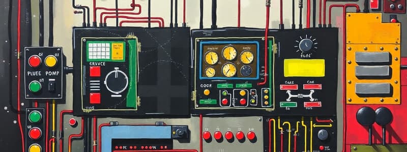
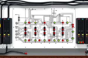
- Illuminated diagrams on control panels should be well-proportioned and use different colours to distinguish track circuit areas.
- Domino-style panels should be used for additional facilities.
- Operating members (e.g., route switches, point switches) should be shown on illuminated diagrams in geographical order.
- Separate illuminated diagrams and consoles may also be provided.
- Route setting is based on the "Entry/Exit" principle. Route setting type installations use two push buttons (one at the entrance and one at the exit).
- Non-route setting installations allow individual operation of points.
Non-Route Setting Installations
- Individual push buttons can be used to clear a signal following point actuation.
- Multiple overlap routes allow selection and setting of desired overlaps.
- Separate pushbuttons for route operation at entrance and exit.
Control Panel Indications
- Provisions for individual point operation.
- Counter for emergency point operation.
- Slotting for adjoining cabins.
- Route cancellation using a group button along with entrance/exit buttons.
- Signal indication of the last operated position cannot be changed when removing power to the system.
- System indicators to show yard position for maintenance personnel.
Point Indications
- Point positions indicated by white/yellow/green lights, near point switches, and white strip lights on the point zone(pushbutton).
- Flashing display shows setting operations.
- Point-locked indication by a small white light.
Route Indications
- Route settings and locking indicated by white lights (at least two) on each track section.
- Route indicating lights are extinguished when route not set.
- Entire route lit by white lights when correctly set.
- Lighting may change to red and back to white when train passes on the route.
Signal Indications
- Stop signal indicated by red light.
- Permissive indicated by yellow.
- Signal 'OFF' normally shown by green or yellow/double yellow lights (flashing in case of failure).
- Indication of 'ON' aspect for shunt signals on a separate post is by white light strip.
Track Circuit Indications
- Occupied track circuits indicated by red lights.
- Lights extinguished when track not occupied.
Power Supply Indications
- Availability indicated, e.g., from Mains/Diesel Generator/Catenary 1 or 2.
Other Indications
- Approach track circuits displayed on the illuminated diagram.
- Advance approach warnings (flashing lights/ audible warnings).
- Signal cancellation by pressing a button.
Route Setting Type
- Interlocking, point setting, and signal clearance follow specific conditions.
- Locking of points in correct route position is essential.
- Level crossings, isolations, and fouling clearances must be validated.
Non Route Setting Type
- Point operations use switches and/or pushbuttons for route selection.
- Entrance/exit buttons are used for clearing signals.
- Point operations need track circuitry checks.
Route Release Circuits
- Route release circuits must be designed for sequential track circuit drop-and-pickup.
- Installations with route setting can release sections if more than 100 routes.
- Non-route setting installations require signal 'ON' before release.
- Sectional release is available for cases of more than 100 routes.
Signal Control Circuits
- Signals will only turn 'OFF' if relevant routes have been set and locked, and track circuits are clear ('OFF' aspect not possible otherwise).
- Emergency operations (with counter recording) are possible for point/route failures.
- Cross-connections and short circuits are prevented.
Point Control Circuits
- Points stay in last set position or may be automatically reset after train passage.
- Point operations possible while interlocking is free and relevant track circuits are clear.
- Emergency point operation is also available.
- Interlocking should be minimal.
- Improper operation (e.g., cross-connection) prevention.
Crank Handle & Siding Control Keys
- Crank handles allow manual point operation (interlocked with signals).
- Point control mechanisms have failure provisions.
Cross Protection Features
- Internal circuits can skip cross-protection if not required.
- External circuits need protection against cross connections and interference.
Control Panel/Control Terminal
- Control panels must use appropriate size displays (showing layouts and features).
- Redundancy/redundant designs (e.g. control display modes) are needed.
- Video display units needed where necessary(e.g., layout display).
- Indications on terminals must conform to those used on other equipment.
Signalling Cables
- Use of at least two cable cores and/or separate cables for maintenance operations.
Signals in Outdoor
- Main signals are multi-color light type.
- Route indicators are available (direction, multi-lamp, stencil types).
- Marker lights for semi-automatic signals are used.
Point Machines
- Point control circuits for protection
- Using crank handles for operation.
Precautions
- Design of components should avoid failure.
- Circuit designs should ensure failsafe operations.
- Maintenance is required for electronic components.
Studying That Suits You
Use AI to generate personalized quizzes and flashcards to suit your learning preferences.


