Podcast
Questions and Answers
What is the main reason for using a BCD counter?
What is the main reason for using a BCD counter?
- To simplify the design of logic circuits.
- To improve the speed of binary calculations.
- To translate binary numbers into decimal numbers for easier human readability. (correct)
- To store data in a more efficient way.
What is the maximum count that a BCD counter can reach?
What is the maximum count that a BCD counter can reach?
9
What is the purpose of a decoder/driver IC in a seven-segment display system?
What is the purpose of a decoder/driver IC in a seven-segment display system?
A decoder/driver IC converts the BCD output from the counter into signals that can be used to light the correct segments of the seven-segment display.
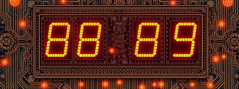
A seven-segment display typically uses seven LED segments arranged in a specific pattern to represent decimal numbers.
A seven-segment display typically uses seven LED segments arranged in a specific pattern to represent decimal numbers.
Which of the following components is NOT typically used in a simple single digit counting system with a BCD counter?
Which of the following components is NOT typically used in a simple single digit counting system with a BCD counter?
What does the circuit diagram show for 'Red' and 'Green' outputs?
What does the circuit diagram show for 'Red' and 'Green' outputs?
What function does the AND gate serve in the circuit diagram?
What function does the AND gate serve in the circuit diagram?
Match the following terms with their corresponding descriptions:
Match the following terms with their corresponding descriptions:
Flashcards
Combinational Logic Circuit
Combinational Logic Circuit
A circuit that operates based on the current state of its inputs and outputs, where the output is determined by the input at that specific moment.
Sequential Logic Circuit
Sequential Logic Circuit
A circuit that utilizes a series of internal states, where each state is determined by the previous state. It may also be influenced by its input.
Binary Coded Decimal (BCD)
Binary Coded Decimal (BCD)
A method of representing decimal numbers using binary digits. Each decimal digit is encoded as a 4-bit binary number.
BCD Counter
BCD Counter
Signup and view all the flashcards
Seven-Segment Display
Seven-Segment Display
Signup and view all the flashcards
Decoder/Driver IC for Seven-Segment Display
Decoder/Driver IC for Seven-Segment Display
Signup and view all the flashcards
Binary to Decimal Conversion
Binary to Decimal Conversion
Signup and view all the flashcards
Automatic System
Automatic System
Signup and view all the flashcards
Clock Signal
Clock Signal
Signup and view all the flashcards
Counter-Based Sequential System
Counter-Based Sequential System
Signup and view all the flashcards
NOT Gate
NOT Gate
Signup and view all the flashcards
AND Gate
AND Gate
Signup and view all the flashcards
NAND Gate
NAND Gate
Signup and view all the flashcards
Seven-Segment Display Character Creation
Seven-Segment Display Character Creation
Signup and view all the flashcards
Decade Counter
Decade Counter
Signup and view all the flashcards
Logic Analyzer
Logic Analyzer
Signup and view all the flashcards
Reset Switch
Reset Switch
Signup and view all the flashcards
Dedicated BCD Counter
Dedicated BCD Counter
Signup and view all the flashcards
Rising Edge
Rising Edge
Signup and view all the flashcards
Logic Gate Design for Seven-Segment Display Characters
Logic Gate Design for Seven-Segment Display Characters
Signup and view all the flashcards
NOR Gate
NOR Gate
Signup and view all the flashcards
XOR Gate
XOR Gate
Signup and view all the flashcards
Sequential Counter
Sequential Counter
Signup and view all the flashcards
Logic Circuit Output
Logic Circuit Output
Signup and view all the flashcards
Permanent Output
Permanent Output
Signup and view all the flashcards
Output State
Output State
Signup and view all the flashcards
Logic Gate Configuration
Logic Gate Configuration
Signup and view all the flashcards
Resetting a Logic System
Resetting a Logic System
Signup and view all the flashcards
Enabling a System
Enabling a System
Signup and view all the flashcards
Disabling a System
Disabling a System
Signup and view all the flashcards
Study Notes
Sequential Systems
- Combining Counters and Logic Circuits: Counters are used to automate systems with repeating patterns, like traffic lights. A combinational logic circuit, linked to a clock and counter, creates these automated systems.
- BCD Counters and Seven-Segment Displays: Binary is cumbersome for humans, requiring translation for decimal display. Binary coded decimal (BCD) counters provide a decimal count (0-9) and a decimal display device for improved readability.
- Binary Coded Decimal (BCD): BCD is a modified binary system with a maximum count of 9 (1001) in decimal. A BCD counter resets after 9.
- Decoder/Driver ICs: Connect BCD counters to seven-segment displays. They decode BCD outputs to appropriate logic signals to light the correct display segments. These ICs also provide enough current to light the display (driver part).
- Single Digit Counting with BCD Counter: A dedicated BCD counter, internally wired to reset after 9, is an alternative to using external AND gates. This simplifies the counting system.
- Seven-Segment Displays: LEDs arranged to form a seven-segment character for display. These common displays are used in counting systems. Multiple characters can be displayed by altering the segment connections and using logic circuits.
Creating Characters on a Seven-Segment Display
- Custom Characters: Seven-segment displays can create characters other than the pre-programmed 0–9. Logic gates (inverters, AND/OR) determine the connections to the display.
- Segment Control: Segments can be connected directly linked to the output or connected by inverters, depending on their dependence on the output conditions for segment operation. This determines if it's an active-high or active-low signal.
Decade Counters
- Decade Counting: These counters count in tens rather than binary. They have one clock input and ten outputs.
- Sequential Activation: Each output (0–9) becomes active in a sequential pattern, one at a time, based on clock pulses.
- Timing and Logic Analyzer: Decade counters are often examined using logic analysers to observe the timed triggering and de-activation of each output. They display when each output pin changes as a result of the clock input changes.
Studying That Suits You
Use AI to generate personalized quizzes and flashcards to suit your learning preferences.


