Podcast
Questions and Answers
What is the calculated value of full load efficiency?
What is the calculated value of full load efficiency?
- 0.88 (correct)
- 0.90
- 0.92
- 0.85
How many total stator slots were calculated based on the assumptions provided?
How many total stator slots were calculated based on the assumptions provided?
- 60
- 66
- 48
- 54 (correct)
What is the equation used for calculating the main dimensions of the machine?
What is the equation used for calculating the main dimensions of the machine?
- D2L = Q / (Co ns) (correct)
- D2L = Co ns / Q
- D2L = Co + ns
- D2L = Q x Co / ns
What is the value of the winding factor (Kw) used in the calculations?
What is the value of the winding factor (Kw) used in the calculations?
How many conductors per slot were ultimately assumed?
How many conductors per slot were ultimately assumed?
What is the main purpose of using induction motors in industries?
What is the main purpose of using induction motors in industries?
Which component differentiates an induction motor from a DC machine?
Which component differentiates an induction motor from a DC machine?
What is the main material used in the magnetic path of the stator in induction motors?
What is the main material used in the magnetic path of the stator in induction motors?
How many sets of windings are required for a 3-phase induction motor?
How many sets of windings are required for a 3-phase induction motor?
What is the primary function of the bearings in an induction motor?
What is the primary function of the bearings in an induction motor?
Which of the following characteristics describes the speed of an induction motor?
Which of the following characteristics describes the speed of an induction motor?
What advantage do laminated cores provide in the stator construction of an induction motor?
What advantage do laminated cores provide in the stator construction of an induction motor?
What materials are commonly used for the outer frame or yoke of an induction motor?
What materials are commonly used for the outer frame or yoke of an induction motor?
What is the primary purpose of a cooling fan in an induction motor?
What is the primary purpose of a cooling fan in an induction motor?
What does the variable 'Co' represent in the output equation of an induction motor?
What does the variable 'Co' represent in the output equation of an induction motor?
What factor influences the shape of the stator slots and consequently affects the performance of the motor?
What factor influences the shape of the stator slots and consequently affects the performance of the motor?
What should be the maximum peripheral speed for the normal design of induction motors?
What should be the maximum peripheral speed for the normal design of induction motors?
Which slot type in an induction motor aids in easy assembly and repair of windings?
Which slot type in an induction motor aids in easy assembly and repair of windings?
What is the ideal range of the ratio between pole pitch and core length to obtain good power factor in induction motors?
What is the ideal range of the ratio between pole pitch and core length to obtain good power factor in induction motors?
Which factor is NOT an advantage of selecting a higher number of stator slots?
Which factor is NOT an advantage of selecting a higher number of stator slots?
How can the turns per phase of an induction motor be calculated?
How can the turns per phase of an induction motor be calculated?
What is the typical ratio of pole pitch/core length to obtain the best overall design in an induction motor?
What is the typical ratio of pole pitch/core length to obtain the best overall design in an induction motor?
Which of the following best describes semiclosed slots in induction motors?
Which of the following best describes semiclosed slots in induction motors?
What is the effect of having a higher number of stator slots on motor design?
What is the effect of having a higher number of stator slots on motor design?
What equation relates the output Q of an induction motor to its dimensions and other parameters?
What equation relates the output Q of an induction motor to its dimensions and other parameters?
What is the typical number of slots per pole per phase for integral slot winding in induction motors?
What is the typical number of slots per pole per phase for integral slot winding in induction motors?
If the output coefficient 'Co' is defined as (11 Bav q Kw cos x 10^-3), what does Bav represent?
If the output coefficient 'Co' is defined as (11 Bav q Kw cos x 10^-3), what does Bav represent?
What is the relationship between the total number of stator conductors and the number of turns per phase?
What is the relationship between the total number of stator conductors and the number of turns per phase?
If the sectional area of the conductors is below 5 mm², which type of conductor is typically used?
If the sectional area of the conductors is below 5 mm², which type of conductor is typically used?
What is the typical value range for current density in stator windings?
What is the typical value range for current density in stator windings?
What is a disadvantage of using a higher current density in stator windings?
What is a disadvantage of using a higher current density in stator windings?
The ratio of slot depth to slot width is typically assumed to be what?
The ratio of slot depth to slot width is typically assumed to be what?
What is the maximum flux density allowed in the stator tooth?
What is the maximum flux density allowed in the stator tooth?
What thickness is generally assumed for coil separators in low voltage machines?
What thickness is generally assumed for coil separators in low voltage machines?
How is the resistance of the stator winding per phase calculated?
How is the resistance of the stator winding per phase calculated?
What is the slot space factor range for stator windings?
What is the slot space factor range for stator windings?
What is the limit for the flux density in the stator core?
What is the limit for the flux density in the stator core?
What is typically more than 25% of the slot area occupied by?
What is typically more than 25% of the slot area occupied by?
To calculate the mean flux density in stator teeth, which formula is used?
To calculate the mean flux density in stator teeth, which formula is used?
In what condition should the slot width be selected?
In what condition should the slot width be selected?
Flashcards are hidden until you start studying
Study Notes
Induction Motor Construction
- Induction motors are commonly used in various industries, from small workshops to large industrial facilities.
- They power diverse equipment like pumps, conveyors, compressors, crushers, and drilling machines.
- Similar to DC motors, but with key differences:
- Laminated stator core for reducing eddy currents and minimizing losses
- Absence of a commutator, simplifying construction and increasing durability
- Uniform and small air gap for efficient magnetic flux transfer
- Nearly constant speed operation
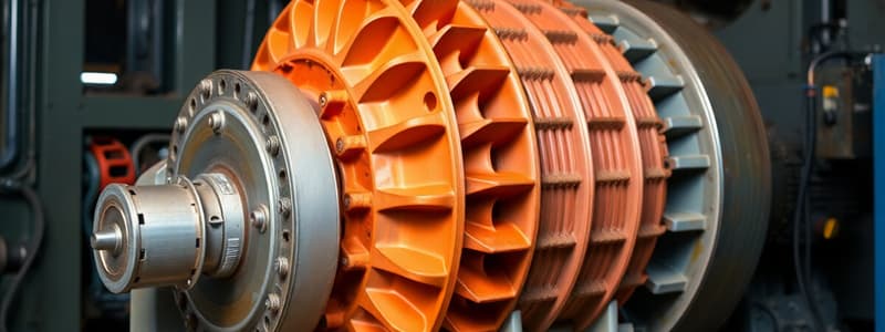
- The motor consists of a stationary stator and a rotating rotor.
- Stator:
- Outer frame made of steel, cast iron, or aluminum alloy
- Laminated stator core inside the frame to reduce eddy currents
- Insulated electrical windings placed within the slots of the laminated stator - three sets for three-phase motors, connected in star or delta configuration.
- Rotor:
- Contains a set of conductors embedded in the rotor core
- This set of conductors forms a closed circuit similar to a squirrel cage.
- Stator:
Output Equation
- The output equation relates the motor's physical and electrical parameters.
- For an 'm' phase motor:
- Output Q (kW) = Input x efficiency
- Input = mVph Iph cos x 10-3 kW
- For a 3-phase motor: Input = 3Vph Iph cos x 10-3 kW
- Assuming Vph = Eph = 4.44 f TphKw, where:
- Vph = phase voltage
- Eph = phase emf
- f = frequency
- Tph = number of turns per phase
- Kw = winding factor
- Output equation simplifies to:
- Q = (11 Bav q Kw cos x 10-3) D2L ns kW
- Where:
- Co = (11 Bav q Kw cos x 10-3) = output coefficient
- D = Diameter of stator
- L = Gross core length
- ns = Synchronous speed in rpm
- Bav = Average flux density
- q = Specific electric loading (air gap flux per pole)
Main Dimensions (D & L)
- The output equation relates D2L to the motor's output.
- Design considerations for achieving optimal ratios between length (L) and pole pitch (pD/p):
- Minimum cost: 1.5 to 2.0
- Good efficiency: 1.4 to 1.6
- Good overall design: 1.0 to 1.1
- Good power factor: 1.0 to 1.3
- To optimize power factor, the following relation is usually assumed for separating D and L:
- Pole pitch/Core length = 0.18/pole pitch
- D = 0.135PvL (where D and L are in meters)
Peripheral Speed
- For typical induction motors, the calculated diameter should ensure a peripheral speed below 30 m/s.
- Specially designed rotors can achieve peripheral speeds up to 60 m/s.
Stator Design
- Stator core and slots:
- Stator slots are typically either open or semi-closed.
- Open slots:
- Slot opening equal to the slot width.
- Easier winding assembly and repairs.
- Higher air gap contraction factor, resulting in poorer power factor.
- Rarely used in three-phase induction motors.
- Semi-closed slots:
- Slot opening smaller than slot width.
- More difficult and time-consuming winding assembly, leading to higher costs.
- Better air gap characteristics compared to open slots.
- Tapered slots:
- Slot opening smaller than slot width.
- Slot width varies from top to bottom, with minimum width at the bottom.
- Offer advantages similar to semi-closed slots.
- Selection of Stator Slots:
- The number of slots significantly affects the motor's weight, cost, and operating characteristics.
- Advantages of higher number of slots:
- Reduced leakage reactance.
- Reduced tooth pulsation losses.
- Higher overload capacity.
- Disadvantages of higher number of slots:
- Increased cost.
- Increased weight.
- Increased magnetizing current.
- Increased iron losses.
- Poorer cooling.
- Increased temperature rise.
- Reduction in efficiency.
- General guidelines:
- Three or more slots per pole per phase for integral slot windings.
- 3.5 slots per pole per phase for fractional slot windings.
- Stator slot pitch at the air gap surface (tss) should be between 1.5 to 2.5 cm.
- tss = pD/Sss (where Sss is the number of stator slots)
- Turns per phase:
- From the EMF equation (Eph = 4.44fFTphkw):
- Tph = Eph/ 4.44fFkw
- Induced emf (Eph) is typically assumed equal to the applied voltage per phase.
- Flux per pole = Bav x pDL/P
- Winding factor (Kw) can be assumed as 0.955 for full pitch distributed winding unless otherwise specified.
- From the EMF equation (Eph = 4.44fFTphkw):
- Number of conductors per phase (Zph):
- Zph = 2 x Tph
- Total number of stator conductors (Z) = 6 Tph
- Conductors per slot (Zs) = Z/Ss (integer for single layer winding and even number for double layer winding)
- Conductor cross-section:
- Area of cross-section of stator conductor (as) estimated from stator current per phase (Is) and current density (ds).
- as = Is / ds
- Stator current per phase: Is = Q / (3Vph cos ?)
- Advantages of higher current density:
- Smaller cross-section.
- Reduced weight.
- Lower cost.
- Disadvantages of higher current density:
- Increased resistance.
- Higher copper losses.
- Increased temperature rise.
- Lower efficiency.
- Typically, 3 to 5 amps current density for stator windings.
- Circular conductors for sectional areas below 5 mm2.
- Rectangular conductors for areas above 5 mm2, with a width to thickness ratio of 2.5 to 3.5.
- Stator slot area:
- Occupied by conductors and insulation (over 25% for insulation).
- Slot space factor = Copper area in the slot / Area of each slot (between 0.25 and 0.4)
- Detailed dimension of the slot can be estimated.
- Slot design:
- Full-pitched double layer windings typically employed for stator windings with even number of conductors per slot.
- Slot width should be balanced to avoid mechanically weak teeth and exceeding permissible flux density (1.6 to 1.8 Tesla).
- Slot depth should not be excessive to avoid increasing leakage reactance, with a depth to width ratio of 3 to 5 generally recommended.
- Slot insulation:
- Slot liner with thickness 0.5 mm to 0.7 mm.
- Coil separator with thickness 0.5 to 0.7 mm (low voltage) or 0.8 to 1.2 mm (high voltage)
- Wedge (3.5 to 5 mm) to hold coils in position.
- Slot lip (1.0 to 2.0 mm).
Length of Mean Turn (lmt)
- lmt = 2L + 2.3 tp + 0.24 (where L is gross length of stator and tp is pole pitch in meters)
Resistance of Stator Winding (rs)
- rs = (0.021 x lmt x Tph)/ as (where lmt is in meters and as is in mm2)
Copper Losses in Stator Winding
- Total copper losses = 3 (Is)2 rs
Flux Density in Stator Tooth
- Calculated at 1/3rd height from the narrow end of the tooth.
- Diameter at 1/3rd height (D'): D' = D + 1/3 x hts x 2 (hts = height of stator slot)
- Slot pitch at 1/3rd height (t's): t's = pxD'/Ss
- Tooth width at this section (b't): b't = t's - bs (bs = slot width)
- Area of one stator tooth (a't): a't = b't x li (li = length of tooth)
- Area of all stator teeth per pole (A't): A't = b't x li x number of teeth per pole
- Mean flux density in stator teeth (B't): B't = F/A't (F = flux)
- Maximum flux density in stator teeth should be less than 1.5 times B't.
Depth of Stator Core
- The solid portion below the slots.
- Flux density in stator core (Bc) is typically 1.2 to 1.4 Tesla.
- Flux in stator core section (Fc): Fc = ½ F
- Area of stator core (Ac): Ac = F/2Bc
- Area of stator core (Ac): Ac = Li x dcs
- Depth of the core: dcs = Ac / Li (dcs = depth of stator core)
Outer Diameter of Stator Core
- Do = D + 2hss (where hss = height of stator slot)
Example Design (30 kW Induction Motor)
- Given: 30 kW, 440 V, 3-phase, 6 pole, 50 Hz, delta connected squirrel cage induction motor.
- Assumed values:
- Specific magnetic loading (Bav) = 0.48 Tesla
- Specific electric loading (q) = 26000 Ac/m
- Full load efficiency (?) = 0.88
- Full load power factor (cosF) = 0.86
- Winding factor (Kw) = 0.955
- Calculated values:
- Main dimensions (D & L):
- D2L = Q/ (Co ns) m
- Co = 11 Bav q Kw ?cosF x 10-3 = 99.2
- ns = 16.67 rps
- D2L = 30/(99.2 x 16.67) = 0.0182 m3
- D = 0.33 m and L = 0.17 m.
- No. of stator turns (Tph):
- F = (pDL/p) Bav = 0.0141 wb
- Assuming Eph = Vph = 440 volts
- Tph = Eph / 4.44fFkw = 148.
- No. of stator slots (Sss):
- Assuming 3 slots/pole/phase: Sss = 3 x 3 x 6 = 54
- No. of conductors per slot (Zs):
- Total no of conductors = 148 x 2 = 296
- No.of conductors /slot = 296/54 = 5.5
- Revised no.of turns/phase = 162, with 76 conductors/slot.
- Main dimensions (D & L):
Studying That Suits You
Use AI to generate personalized quizzes and flashcards to suit your learning preferences.
