Podcast
Questions and Answers
What is the primary function of the Philadelphia Fire Department's engine company apparatus fire pump as described in the manual?
What is the primary function of the Philadelphia Fire Department's engine company apparatus fire pump as described in the manual?
- To supply general information about the engine company apparatus fire pump. (correct)
- To outline strict regulations for firehouse cooking and maintenance.
- To serve as a comprehensive guide for advanced medical response during fire incidents.
- To provide a detailed historical account of firefighting techniques used in Philadelphia.
According to the manual, what is the expectation for each member regarding the implementation of the fire pump procedures?
According to the manual, what is the expectation for each member regarding the implementation of the fire pump procedures?
- To exercise appropriate control based on their rank during the implementation of the manual. (correct)
- To defer all operational decisions to the most senior officer present.
- To strictly adhere to a pre-defined checklist, regardless of the situation.
- To immediately report any deviations from the manual to the Fire Commissioner.
Why does the Philadelphia Fire Department require all engine company members to have a basic understanding of the apparatus, the pump panel, and the general operations of the fire pump?
Why does the Philadelphia Fire Department require all engine company members to have a basic understanding of the apparatus, the pump panel, and the general operations of the fire pump?
- To comply with federal regulations mandating cross-training in all aspects of fire service.
- To make pumping operations manageable through proper information and training. (correct)
- To ensure that all members can perform advanced maintenance on the fire trucks, reducing costs.
- To prepare members for potential promotional exams and career advancement opportunities.
According to the manual, what range of years do the PFD engine fleets consist of?
According to the manual, what range of years do the PFD engine fleets consist of?
What capability does the capacity rating reflect for the engine fleet in the Philadelphia Fire Department, according to the manual?
What capability does the capacity rating reflect for the engine fleet in the Philadelphia Fire Department, according to the manual?
What is the functional principle behind the fire pumps used by the Philadelphia Fire Department, as described in the manual?
What is the functional principle behind the fire pumps used by the Philadelphia Fire Department, as described in the manual?
According to the manual, what is a key distinction in the operation of single-stage versus two-stage pumps?
According to the manual, what is a key distinction in the operation of single-stage versus two-stage pumps?
According to the manual, in a two-stage pump operating in 'PRESSURE' (series) mode, what happens to the water flow?
According to the manual, in a two-stage pump operating in 'PRESSURE' (series) mode, what happens to the water flow?
According to the manual, under what circumstances does the manufacturer recommend using the 'VOLUME' (parallel) setting on a two-stage pump?
According to the manual, under what circumstances does the manufacturer recommend using the 'VOLUME' (parallel) setting on a two-stage pump?
What is the operational outcome of using the 'VOLUME' stage setting, according to the manual?
What is the operational outcome of using the 'VOLUME' stage setting, according to the manual?
According to the manual, what does the Compound Gauge (intake) indicate?
According to the manual, what does the Compound Gauge (intake) indicate?
According to the manual, why is it important to note the static pressure on the Compound Gauge?
According to the manual, why is it important to note the static pressure on the Compound Gauge?
According to the manual, what does the drop in pressure on the Compound Gauge reflect after opening a discharge line?
According to the manual, what does the drop in pressure on the Compound Gauge reflect after opening a discharge line?
According to the manual, what range should you want your residual pressure to stay above?
According to the manual, what range should you want your residual pressure to stay above?
According to the manual, what does the Master Pressure Gauge (discharge) display?
According to the manual, what does the Master Pressure Gauge (discharge) display?
What are Test Gauge Ports primarily used for, as described in the manual?
What are Test Gauge Ports primarily used for, as described in the manual?
According to the manual, what function does the Tachometer serve during pump operations?
According to the manual, what function does the Tachometer serve during pump operations?
What is the normal operating temperature range for a diesel engine, while pumping, according to the manual?
What is the normal operating temperature range for a diesel engine, while pumping, according to the manual?
What is the minimum acceptable reading on the Engine Oil Pressure Gauge, according to the manual?
What is the minimum acceptable reading on the Engine Oil Pressure Gauge, according to the manual?
According to the manual, what does the Throttle control?
According to the manual, what does the Throttle control?
According to the manual, what do Individual Discharge Gauges indicate?
According to the manual, what do Individual Discharge Gauges indicate?
What is the typical purpose of Flow Meters, according to the manual?
What is the typical purpose of Flow Meters, according to the manual?
What is the procedure when opening and closing Individual Discharge Gates, according to the manual?
What is the procedure when opening and closing Individual Discharge Gates, according to the manual?
According to the manual, what is the function of the Tank-To-Pump Valve?
According to the manual, what is the function of the Tank-To-Pump Valve?
According to the manual, what does the Tank Fill Valve allow?
According to the manual, what does the Tank Fill Valve allow?
According to the manual, what is the purpose of the Pump Cooler, Booster Cooler, or Circulating Valve?
According to the manual, what is the purpose of the Pump Cooler, Booster Cooler, or Circulating Valve?
Under what specific condition should the Engine Cooler be opened, as described in the manual?
Under what specific condition should the Engine Cooler be opened, as described in the manual?
According to the manual, what services should the Discharge Relief Valve be used on?
According to the manual, what services should the Discharge Relief Valve be used on?
What is the primary function of Intake Relief Valves, as outlined in the manual?
What is the primary function of Intake Relief Valves, as outlined in the manual?
According to the manual, what is the purpose of the Priming Pump Reservoir and what type of oil does it hold?
According to the manual, what is the purpose of the Priming Pump Reservoir and what type of oil does it hold?
According to the manual, what does the Primer do?
According to the manual, what does the Primer do?
According to the manual, what does the Transfer Valve control?
According to the manual, what does the Transfer Valve control?
What is the purpose of the Main Suctions, as noted in the manual?
What is the purpose of the Main Suctions, as noted in the manual?
What is the purpose of the Auxiliary Suctions, as outlined in the manual?
What is the purpose of the Auxiliary Suctions, as outlined in the manual?
What is the recommendation for Strainers, as described in the manual?
What is the recommendation for Strainers, as described in the manual?
According to the manual, what are Discharge Drains and Bleeders designed to do?
According to the manual, what are Discharge Drains and Bleeders designed to do?
According to the manual, what is the Master Pump Drain designed to do and what is the procedure?
According to the manual, what is the Master Pump Drain designed to do and what is the procedure?
According to the manual, what information is provided on the UL Plate?
According to the manual, what information is provided on the UL Plate?
According to the procedure, what initial steps should be taken inside the cab when placing an engine into pump operation?
According to the procedure, what initial steps should be taken inside the cab when placing an engine into pump operation?
What is the first step in out of cab procedures when placing an engine into pump?
What is the first step in out of cab procedures when placing an engine into pump?
According to the manual when placing an engine into pump, what confirmation should be checked to ensure the pump is engaged?
According to the manual when placing an engine into pump, what confirmation should be checked to ensure the pump is engaged?
What is the consequence of failing to slowly increase or decrease the pressure when operating the throttle?
What is the consequence of failing to slowly increase or decrease the pressure when operating the throttle?
What could be the problem if, after priming, the pump fails to achieve draft and water is not being drawn into the pump?
What could be the problem if, after priming, the pump fails to achieve draft and water is not being drawn into the pump?
What operational impact would result from a partially closed Auxiliary Suction valve while supplying a master stream device if the Main Suction is insufficient alone?
What operational impact would result from a partially closed Auxiliary Suction valve while supplying a master stream device if the Main Suction is insufficient alone?
How does the Pressure Relief System on a fire pump protect firefighters and equipment during fireground operations?
How does the Pressure Relief System on a fire pump protect firefighters and equipment during fireground operations?
How can Individual Discharge Gauges assist in troubleshooting issues related to pressure loss in a multi-line fire attack scenario?
How can Individual Discharge Gauges assist in troubleshooting issues related to pressure loss in a multi-line fire attack scenario?
Flashcards
Centrifugal Fire Pump
Centrifugal Fire Pump
Pumps rotate water to achieve centrifugal force.
Volume Mode
Volume Mode
Operates in volume mode; found in single-stage pumps.
Volume (Parallel) Setting
Volume (Parallel) Setting
A setting where impellers receive water directly from the pump intake, maximizing discharge flow.
Pressure Mode
Pressure Mode
Signup and view all the flashcards
Pressure (Series) Setting
Pressure (Series) Setting
Signup and view all the flashcards
Compound Gauge (Intake)
Compound Gauge (Intake)
Signup and view all the flashcards
Residual Pressure
Residual Pressure
Signup and view all the flashcards
Master Pressure Gauge (Discharge)
Master Pressure Gauge (Discharge)
Signup and view all the flashcards
Tachometer
Tachometer
Signup and view all the flashcards
Engine Water Temperature Gauge
Engine Water Temperature Gauge
Signup and view all the flashcards
Engine Oil Pressure Gauge
Engine Oil Pressure Gauge
Signup and view all the flashcards
Throttle
Throttle
Signup and view all the flashcards
Individual Discharge Gauges
Individual Discharge Gauges
Signup and view all the flashcards
Flow Meter
Flow Meter
Signup and view all the flashcards
Individual Discharge Gates
Individual Discharge Gates
Signup and view all the flashcards
Tank-To-Pump Valve
Tank-To-Pump Valve
Signup and view all the flashcards
Tank Fill Valve
Tank Fill Valve
Signup and view all the flashcards
Water Level Indicator
Water Level Indicator
Signup and view all the flashcards
Pump Cooler/Circulating Valve
Pump Cooler/Circulating Valve
Signup and view all the flashcards
Engine Cooler
Engine Cooler
Signup and view all the flashcards
Discharge Relief Valve
Discharge Relief Valve
Signup and view all the flashcards
Intake Relief Valves
Intake Relief Valves
Signup and view all the flashcards
Primer
Primer
Signup and view all the flashcards
Transfer Valve
Transfer Valve
Signup and view all the flashcards
Main Suctions
Main Suctions
Signup and view all the flashcards
Auxiliary Suctions
Auxiliary Suctions
Signup and view all the flashcards
Discharge Drains and Bleeders
Discharge Drains and Bleeders
Signup and view all the flashcards
Master Pump Drain
Master Pump Drain
Signup and view all the flashcards
UL Plate
UL Plate
Signup and view all the flashcards
Study Notes
General Information
- This manual provides information about the engine company apparatus fire pump, for Philadelphia Fire Department engine company members.
- Exercising appropriate control, as dictated by rank, is each member's responsibility when implementing this manual.
- A basic understanding of the apparatus, pump panel, and fire pump operations is required for all engine company members.
- Pumping apparatus can be simplified with the correct education and training.
The Pump
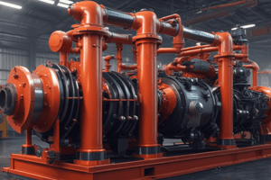
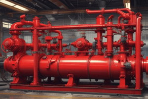
- The PFD engine fleet includes apparatus from 1995 to the present, equipped with One or Two-Stage 1500 Gallon per Minute Hale and Waterous pumps.
- The capacity rating reflects the pumps capability to discharge 1500 GPM at draft.
- With a constant static water supply, pumps can produce more than their rated capacity.
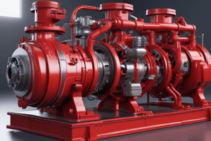
- Centrifugal fire pumps rotate water to achieve centrifugal force.
- Water enters the impeller's eye, moved through the impeller into the casing, enlarging near the discharge port.
Volume & Pressure
- Single-stage pumps operate in volume mode.
- Two-stage pumps operate in pressure or volume mode.
- In PRESSURE (series) mode, the output from the first impeller goes to the second, adding pressure and resulting in higher pressure but lower GPM.
- In VOLUME (parallel) mode, both impellers receive water from the pump intake, combining their flows and resulting in lower pressure but greater GPM.
- The manufacturer recommends the VOLUME setting for pumping more than 50% (750 GPMs) of the pumps max rated capacity of 1500 GPM, such as for master streams.
PFD Pump Panel
- Compound Gauge (intake): Located top left of pump panel displays available water pressure coming into pump from pressurized water source. Note static pressure before opening discharge. The pressure drop shows PSI loss from the opened discharge line.
- The remaining pressure to stay above 20 PSI, is the residual pressure, and gives a true reading when tip is open.
- Master Pressure Gauge (discharge): Located on the pump panel top right, displays the total pressure the pump is producing.
- Test Gauge Ports: Used during pump tests to verify accuracy of the compound gauge and master pressure gauge.
- Tachometer: Measures engine speed in RPMs. During pump operations monitor the RPMs to ensure they are at expected speeds consistent with the PSI on the Pressure gauges.
- Engine Water Temperature Gauge: Normal operating temperature for a diesel engine is 180 – 197 degrees.
- Engine Oil Pressure Gauge: Should not read below 10 PSI.
- Throttle: Controls the speed of the engine. As RPM’s increase, pressure increases. Whether the apparatus has a manual or electronic throttle control always increase and decrease the pressure slowly to prevent water hammer.
- Individual Discharge Gauges: Indicates pressure at the discharge gate.
- Individual Pressure Gauge: Displays pressure slightly different from the Master Pressure Gauge; critical for setting correct pressure when running multiple lines off the same engine.
- Flow Meter: Indicates water flow in GPMs typically on 5” discharge gates or some Deck-Gun Monitors, Squrts, Water-Towers, etc.
- Individual Discharge Gates: Ball valves control flow of water at each discharge, open and close, slowly.
- Tank-To-Pump Valve: Controls the flow of water between the tank and the pump.
- Tank Fill Valve: Allows water to pass from the pump into the water tank, refill your tank as soon as possible.
- Water Level Indicator: Displays water level in tank. PFD engines have 500-gallon tanks.
- Pump Cooler, Booster Cooler or Circulating Valve: Directs water from the discharge side of the pump back into the water tank and should be opened on EVERY pump operation.
- Engine Cooler: Keep closed redirecting water from the pump around the engine cooling system, only open when engine water gauge reads 205 degrees or greater, and consider taking additional measures when at risk of overheating.
- Discharge Relief Valve: Directs water from the discharge side of the pump back to the intake side. It must be used on all services other than booster line in order to act as a safety mechanism and prevent any unwanted increased pressure on any discharge line.
- Intake Relief Valves: There are three (one on the driver side and two on the officer side.) Relieves pressure from water coming into the pump (mostly used in a relay) should be left at highest level.
- Priming Pump Reservoir: Containing and using 30W oil (95-96 KME, 03-04 LaFrance). it supports priming systems and all pumpers 2009-Present have air actuated primers.
- Primer: Displaces air from the pump when activated and creates a negative pressure when drafting allowing atmospheric pressure to push water into the pump.
- Transfer Valve: Controls what stage the pump is in.
- Most PFD Pumpers are 2 stage pumps: Pressure and Volume. Only change modes when throttled down to idle. In “pressure” (series) setting, the output from the impeller being supplied by the pump intake is sent to the second impeller where additional pressure is added before being discharged, resulting in a higher pressure but lower GPM. In the “volume” (parallel) setting, both impellers receive water directly from the pump intake so the discharge flow is the sum of both impellers, generally use this setting when pumping more than 50 % of the pumps rated capacity (i.e., master streams.) Lower pressure, greater GPM.
- Main Suctions (two): All pumpers have two side 6” NST intakes, which allow water to flow directly into the pump.
- Auxiliary Suctions (two): Gated side 2 ½” NST intakes that allow water to flow into the pump. Intake connections when using 3” supply line (i.e., first-in situations or when adding a supplemental supply line).
- Strainers: Check regularly as they rust over time and prolong the life of the pump.
- Discharge Drains and Bleeders: Designed to bleed pressure from the hose line attached to the gate, located between the gate and the outlet, and may be opened up before you open the intake gate to dispel air.
- Master Pump Drain: Designed to drain the pump of water and never be opened under pressure, and to disconnect from the hydrant before opening you must take the apparatus out of pump.
- UL Plate: Lists the rated capacity of the pump.
Placing an Egine Into Pump
In Cab Procedures
- Properly place the apparatus and come to a complete stop.
- Place the transmission into neutral and set the parking brake.
- Slowly engage the pump, switching from road to pump,.
- Place transmission in DRIVE and check for green OK TO PUMP confirmation light and or rise in RPMs.
Out of Cab Procedures
- Ensure you are on the correct radio channel and wearing your helmet and appropriate gloves.
- Properly chock the rear wheel and check to ensure the green pump engaged light is lit.
- Ensure that the tank to pump valve is open, check the Master Pressure Gage to ensure you have the correct operating pressure at idle engine speed.
- Charge the correct hose line and throttle up to correctly calculated pressure (psi).
- Set the Pressure relief valve and establish a water supply.
Studying That Suits You
Use AI to generate personalized quizzes and flashcards to suit your learning preferences.