Podcast
Questions and Answers
Flashcards
A320 Electrical System
A320 Electrical System
The A320 electrical power system uses a three-phase 115/200V AC system at 400 Hz and a 28V DC system.
Generator Network Supply
Generator Network Supply
Each of the aircraft's three generators can independently supply the entire electrical network.
AC Generator Sources
AC Generator Sources
Two main generators (GEN 1 & GEN 2) that are engine-driven, and one APU generator.
Generator Control Unit (GCU)
Generator Control Unit (GCU)
Signup and view all the flashcards
External Power
External Power
Signup and view all the flashcards
Emergency Generator
Emergency Generator
Signup and view all the flashcards
Static Inverter
Static Inverter
Signup and view all the flashcards
Transformer Rectifiers (TRs)
Transformer Rectifiers (TRs)
Signup and view all the flashcards
Essential Transformer Rectifier (ESS TR)
Essential Transformer Rectifier (ESS TR)
Signup and view all the flashcards
Aircraft Batteries
Aircraft Batteries
Signup and view all the flashcards
Battery Charge Limiter (BCL)
Battery Charge Limiter (BCL)
Signup and view all the flashcards
Circuit Breaker Types
Circuit Breaker Types
Signup and view all the flashcards
Wing Tip Brakes (WTB) C/Bs
Wing Tip Brakes (WTB) C/Bs
Signup and view all the flashcards
Monitored C/B Panels
Monitored C/B Panels
Signup and view all the flashcards
C/B TRIPPED Caution
C/B TRIPPED Caution
Signup and view all the flashcards
Generator Priority
Generator Priority
Signup and view all the flashcards
AC BUS Supply
AC BUS Supply
Signup and view all the flashcards
AC BUS 1 normal supply
AC BUS 1 normal supply
Signup and view all the flashcards
Generator Failure Response
Generator Failure Response
Signup and view all the flashcards
AC BUS 2 and ESS TR
AC BUS 2 and ESS TR
Signup and view all the flashcards
TR Failure Response
TR Failure Response
Signup and view all the flashcards
TR 1 and TR 2 Failure
TR 1 and TR 2 Failure
Signup and view all the flashcards
Total Power Loss
Total Power Loss
Signup and view all the flashcards
MAN ON pb
MAN ON pb
Signup and view all the flashcards
COMMERCIAL pb sw OFF
COMMERCIAL pb sw OFF
Signup and view all the flashcards
EXT PWR AVAIL
EXT PWR AVAIL
Signup and view all the flashcards
MAINT BUS switch
MAINT BUS switch
Signup and view all the flashcards
SMOKE configuration
SMOKE configuration
Signup and view all the flashcards
BAT 1(2) ind
BAT 1(2) ind
Signup and view all the flashcards
BAT 1 (2) pb sw Auto
BAT 1 (2) pb sw Auto
Signup and view all the flashcards
BAT 1 (2) pb sw OFF
BAT 1 (2) pb sw OFF
Signup and view all the flashcards
IDG FAULT
IDG FAULT
Signup and view all the flashcards
GEN 1 (2) pb sw ON
GEN 1 (2) pb sw ON
Signup and view all the flashcards
APU GEN pb sw ON
APU GEN pb sw ON
Signup and view all the flashcards
GEN 1 LINE pb sw
GEN 1 LINE pb sw
Signup and view all the flashcards
Starting the APU
Starting the APU
Signup and view all the flashcards
Electronic Control Box (ECB)
Electronic Control Box (ECB)
Signup and view all the flashcards
Normal APU shutdown with APU Master Switch
Normal APU shutdown with APU Master Switch
Signup and view all the flashcards
APU START push button function
APU START push button function
Signup and view all the flashcards
APU lubrication system
APU lubrication system
Signup and view all the flashcards
ECB fuel flow control
ECB fuel flow control
Signup and view all the flashcards
Selecting the APU MASTER SW to ON
Selecting the APU MASTER SW to ON
Signup and view all the flashcards
APU MASTER SW FAULT light illumination
APU MASTER SW FAULT light illumination
Signup and view all the flashcards
APU startup altitude
APU startup altitude
Signup and view all the flashcards
APU system page on ECAM
APU system page on ECAM
Signup and view all the flashcards
APU running after manual shutdown.
APU running after manual shutdown.
Signup and view all the flashcards
AVAIL light with engines off
AVAIL light with engines off
Signup and view all the flashcards
External power availability and BATT switch position
External power availability and BATT switch position
Signup and view all the flashcards
Maximum altitude with battery only
Maximum altitude with battery only
Signup and view all the flashcards
APU fuel pump operation
APU fuel pump operation
Signup and view all the flashcards
Altitude for APU BLEED valve automatically closed
Altitude for APU BLEED valve automatically closed
Signup and view all the flashcards
APU FIRE with nobody in the cockpit
APU FIRE with nobody in the cockpit
Signup and view all the flashcards
Basic element of the APU
Basic element of the APU
Signup and view all the flashcards
Fire on ground or in flight
Fire on ground or in flight
Signup and view all the flashcards
APU fire test with battery power
APU fire test with battery power
Signup and view all the flashcards
Starter engages with closed intake
Starter engages with closed intake
Signup and view all the flashcards
APU may obtain power:
APU may obtain power:
Signup and view all the flashcards
The APU can be shut down outside the aircraft:
The APU can be shut down outside the aircraft:
Signup and view all the flashcards
Study Notes
Description
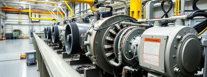
- The basic element of the APU is a single shaft gas turbine, which delivers power for driving the accessory gearbox (electrical generator) and bleed air (engine starting and pneumatic supply).
- APU has an integral independent lubrication system for lubrication and cooling
- An Electronic Control Box (ECB) is a full authority digital electronic controller that performs APU system logic for all modes of operation, such as sequence/monitoring of start, speed/temperature monitoring, and bleed air monitoring/shutdown.
- ECB also controls fuel flow
APU Start
- To start the APU, BAT 1 and 2 push buttons must be selected to ON, unless external power is available.
- Alternatively, if external power is available, BAT 1 and 2 push buttons do not need to be selected ON, and should remain in the lights out position
- With battery power only, an APU fire test will have the APU FIRE pushbutton, SQUIB, and DISCH lights illuminated
- The APU can obtain power for starting from ground services, normal aircraft supply, aircraft batteries, or a combination with external power
- Before start, APU MASTER SW selection initiates an automatic computer self-test, air intake flap opening, and fuel pressure supply.
- Starter engages if the air intake is closed and the MASTER SW and START pushbuttons are ON
- Maximum altitude for APU start using batteries only is 25,000 ft
- Maximum altitude for normal APU operation is 39,000 feet
- If external power and the APU START pushbutton AVAIL lights are illuminated with engines off, external power is the source for aircraft buses
Indications
- ECAM displays the APU system page when selected by the crew or automatically when the APU is started and AC power is available.
- An amber FUEL LO PR indication appears during APU start if low fuel pressure is detected.
- A FLAP OPEN indication displays in amber when the APU air inlet flaps are fully open; the indication is normally displayed in green
APU Shutdown
- Normal APU shutdown after the APU Master Switch is released occurs without delay in all cases
- A delay occurs if bleed air was in use
- If APU bleed was used, after a manual shut down sequence, the APU keeps running for 60 seconds
- On the ground, the No Break Power Transfer function is inhibited if APU shutdown is triggered by the ECB, the REFUEL/DEFUEL panel, the APU FIRE pushbutton, or emergency control on the external power panel
- APU cannot be shut down from outside the aircraft via the APU SHUT OFF pushbutton on External Power Panel
APU Bleed
- APU bleed valve closes at 29,000 feet descending, automatically by the ECB
- Maximum Altitude for APU bleed is 22,000 ft
- APU can be used with wing anti-ice on but only for electrical power; avoid opening the APU bleed valve while using wing anti-ice
- It is possible to use simultaneously packs and Lp ground unit during long stops in a hot airfield if the external temperature is greater than 50 deg.C.
APU Fire Protection
- APU MASTER SW pushbutton FAULT light comes on for fire on ground or in flight
- If there is an APU FIRE and nobody is in the cockpit, an automatic APU EMER (emergency) shutdown occurs and the fire bottle discharges automatically on the ground, but in the air, an APU EMER shut down will occur and the APU fire bottle will be discharged automatically.
- Fire protection is available if APU start is initiated on battery power only
- During an APU fire test, the automatic shutdown of the APU on the ground will not occur while the flight crew is performing this test
APU Fuel
- APU is supplied from the left or right fuel feed line
- fuel pump runs all the time when the APU is running
Bleed Air and Packs when APU is running
- In A319/320/321 when APU is supplying Bleed air, with the pack flow selector to low, the packs are high and A321 is Normal.
- HI flow is automatically selected regardless of PACK FLOW selector position because air is only being supplied by the APU.
Air Conditioning/Pressurization/Ventilation
- Conditioned air is distributed to the cockpit, avionics bay, and cabin as well as holds 1 and 2 only.
- The crew should select RAM AIR ON for dual pack failure or smoke removal
- Normal maximum cabin altitude is 9,550 ft +/- 350 ft
- Maximum negative differential pressure for the cabin is 1 psi
- The different sources of air for air conditioning and pressurization are engine bleed air and recirculated air, or if selected, APU bleed air and recirculated air
- During exterior preflight on a warm day, expect to find the avionics ventilation system INLET and EXTRACT valves open
- During engine start, pack flow control valves automatically close
- Each aircraft zone's temperature is optimized by a TRIM AIR valve
- Normal pressurization occurs after rotation
- Normal depressurization occurs on landing touchdown
- Pack flow controller should be set to LO with a low passenger load to reduce bleed air demand and improve fuel efficiency
- Pressurization controllers receive inputs from the LGCIU, ADIRU, FMGS, and EIU
- In flight below 12,500ft, the ram air valve can provide an emergency source of conditioned air during non-pressurized flight.
Controls and Indications
- Bleed air supplied from the APU, pack flow is automatically selected to normal flow
Overheat
- Hot air "FAULT" light illuminates on the air conditioning panel if the hot air press reg. valve closes and the trim air valves open or in closed position.
- Placing the avionics ventilation system in the smoke configuration de-energizes the blower fan, allows the extract fan to run, and opens the air conditioning extract valves
- Cabin temperature will be controlled at the upper limit of 30 deg.C
- The outflow valve is fully released on the ground
- 120 % of normal air during engine starting
- When APU is supplying the packs, the pack controller sends a demand signal to increase airflow on the flow in Pack control valve.
- During landing is 70 kts (after 20 seconds delay) by hot
Studying That Suits You
Use AI to generate personalized quizzes and flashcards to suit your learning preferences.


